
Table 10-17.--Maximum Distance Between Supports for Aluminum Tubing
TUBING OUTSIDE
DISTANCE BETWEEN SUPPORTS IN INCHES
DIAMETER (INCHES)
ALUMINUM ALLOY
STEEL
1/8
9-1/2
11-1/2
3/16
12
14
1/4
13-1/2
16
5/16
15
18
3/8
16-1/2
20
1/2
19
23
5/8
22
25-1/2
3/4
24
27-1/2
1
26-1/2
30-1/2
1-1/4
28-1/2
31-1/2
1-1/2
29-1/2
32-1/2
repairs are made with splice sections fabricated with
Unless otherwise specified, where tubing is
flared ends or preset MS sleeves. The splice sections
supported to structure or other rigid members, a
are to be replaced by a permanent repair or new tubing
minimum clearance of 1/16 inch or where related
assembly at the next rework cycle. Temporary or
motion of adjoining components exists, a minimum
emergency repairs should be limited to cases that are
clearance of 1/4 inch is to be maintained. Table 10-17
due to unavailability of equipment, material, or unusual
shows the maximum allowable distance between
circumstances.
supports. Flexible grommets or hose should be used at
points where the tubing passes through bulkheads.
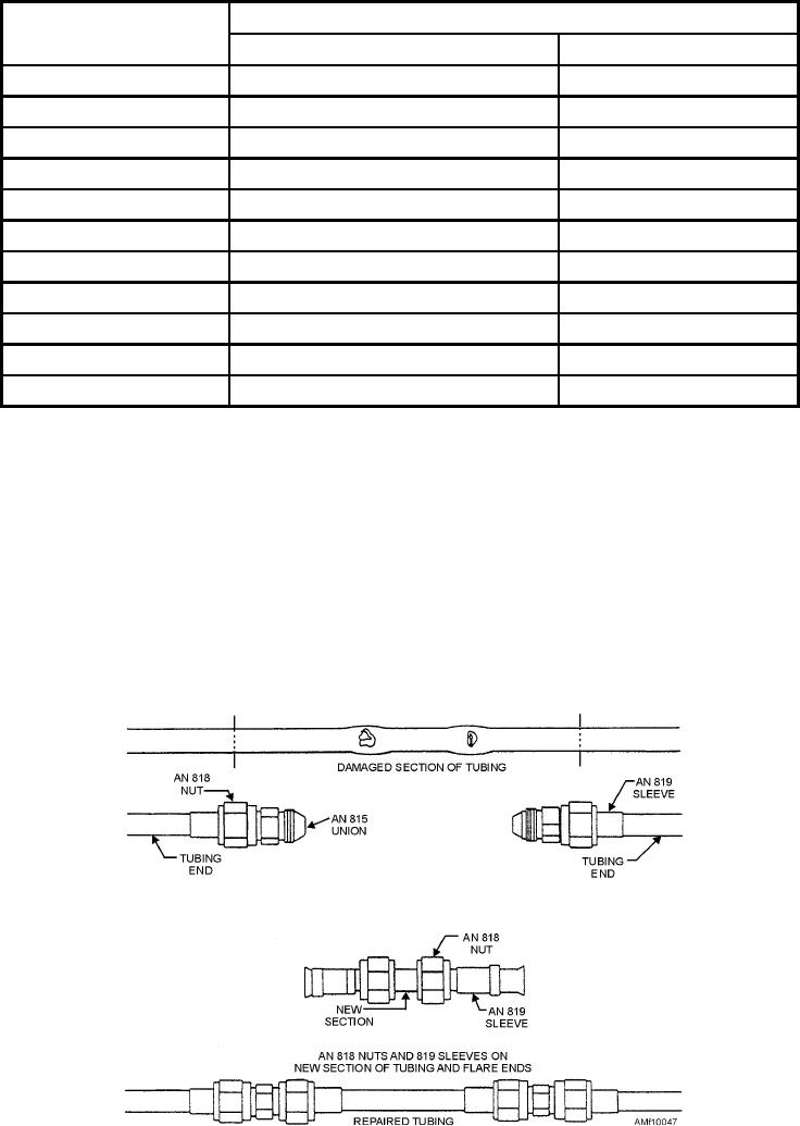
Cut and remove the damaged section of tubing.
Remove the rough edges of the remaining tube ends.
Repair
Clean the tubing ends with a lint-free wiping cloth.
Position the AN818 nuts and AN819 sleeves on
Tube repair is divided into two
the tubing ends (fig. 10-47). Flare the tubing. Install
categories--temporary and permanent. Temporary
Figure 10-47.--Temporary tubing repair.
10-43

