
Several types of operating and control systems
has internal splines and is a loose fit on the external
exist. Those discussed in this course are widely used
splines of the starting motor armature shaft. The rotor is
but none describes a specific support unit.
connected to the pinion and the steel rollers are located
in tapered notches in the shell. Springs and plungers
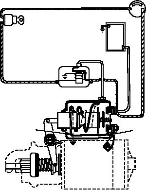
Solenoid
hold the rollers in the position shown in the illustration.
When the solenoid is energized, the drive unit is
On starters that have overrunning clutch drives, a
moved along the armature shaft, and the pinion engages
solenoid is used to shift the pinion into engagement
the ring gear. Should the pinion meet the ring gear but
with the ring gear (fig. 6-69). It also closes a set of
not engage it, the clutch spring compresses; this allows
heavy-duty contacts to complete the circuit from the
the solenoid plunger to continue moving to close the
battery to the starting motor. Mechanical linkage is
contacts and energize the starting motor. As the starting
used to connect the solenoid plunger to the shift lever,
motor starts to rotate, the pinion turns and is engaged
which moves the pinion. Remote control of the
with the ring gear by the action of the clutch spring
solenoid is achieved by a low current control circuit.
expanding. The rotor is not stationary. As the starting
Some systems use a push-button switch or an ignition
motor rotates the shell, the rollers are forced tightly into
switch with a start position. In some systems a relay is
the small end of the tapered notches to cause the shell
used to control current flow to the solenoid, and the
and rotor to rotate together as a unit. The rotor is
remote control circuit is used to control the relay. When
connected to the pinion, which turns the engine. After
the control circuit to the solenoid is completed, a path
the engine begins to run, the ring gear drives the pinion
for current flow is created through the pull-in and the
at a higher speed than that of the starting motor and
hold-in windings. The combined magnetic fields of
tends to work the rollers back toward the large end of
these windings pull the solenoid plunger in so that the
the tapered notches against the springs and plungers.
pinion shifts engage the ring gear and close the
This frees the rotor from the shell and the pinion
heavy-duty contacts of the solenoid.
overruns the starting motor armature shaft, which
While different size wire is used for the two
prevents the starting motor from being driven by the
windings, they have approximately the same number of
engine even though the pinion is still engaged with the
turns. The heavy pull-in winding is needed to pull the
ring gear. When the solenoid de-energizes, a spring
returns the drive unit back to its original position,
disengaging the pinion from the ring gear.
IGNITION
BATTERY
GEAR REDUCTION DRIVEHEADS.--Gear
STARTER
SWITCH
reduction driveheads provide a greater gear reduction
than that of a pinion and ring gear. They are used in
conjunction with Bendix drive units on heavy-duty
starters. The gear on the armature shaft does not engage
directly with the ring gear. It engages an intermediate
gear, which drives the starter pinion. This drive permits
the use of a small starting motor, which runs at high
speed to provide additional starting torque and greater
SOLENOID
cranking power. The armature of a starter of this type
may turn as many as 40 times for each revolution of the
flywheel when cranking an engine.
HOLD-IN
WINDING
PULL-IN
WINDING
Starting Motor Controls
Starting motor controls can be divided into two
groups: operating and safety. The operating controls
provide the operator with the means to start the
STARTER
vehicle's engine. The safety controls prevent the starter
ASf06069
from being operated under conditions that could
Figure 6-69.--Control system for a starter with overrunning
damage the starter or vehicle.
clutch drive.
6-56