
fault must be in the spark plugs, the distributor cap, the
ohmmeter should show continuity between the ground
rotor button, or the high-tension spark plug leads.
and the connector pin. If continuity does not exist,
tighten the bolts holding the control unit to the firewall
To determine where the fault lies, remove the
and recheck. If continuity still does not exist, replace
distributor cap and inspect the metal segments that
the control unit. Reconnect the wiring harness to the
protrude through the cap from the high-tension spark
control unit and distributor.
plug leads and the carbon contact located directly
below the cavity where the high-tension coil lead
NOTE: When installing the wiring harness con-
attaches. Inspect for excessively burnt or bent
nector to the control unit, ensure the ignition switch is
segments, a crack in the distributor cap, or a broken
in the OFF position. Otherwise, the control unit could
carbon contact. If observations indicate that the rotor
be damaged.
button's contact has been hitting the distributor cap's
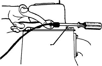
Check the ignition secondary system again; remove
metal segments, the distributor shaft should be checked
the high-voltage cable from the center tower of the
to determine if the shaft bushings are worn.
distributor and hold the cable approximately 1/4 inch
Additionally, the distributor cap should be inspected for
away from the engine (fig. 6-64). Crank the engine and
"tracing," which is a metal powder residue running
check for spark. If there is no spark, replace the control
from segment to segment inside the cap.
unit. Crank the engine again, and if a spark still does not
occur, replace the ignition coil.
Spark Plugs and Leads
SECONDARY ELECTRICAL SYSTEM
If the distributor cap and rotor button seem to be in
TROUBLESHOOTING
order, the individual high-tension spark plug leads must
be checked for continuity. Since radio-resistant wires
The secondary system in the ignition system on
are used extensively in today's SE, the technical
modern SE consists of the high-tension lead from the
manuals should be consulted when checking resistance
coil tower to the center position in the distributor cap,
values on these high-carbon impregnated leads.
the distributor cap and rotor button, the high-tension
By following this "common sense" approach to
spark plug leads from their respective positions in the
troubleshooting, the secondary side of the ignition
distributor cap to the spark plugs, and the spark plugs
system and all problems will be covered, and the
themselves. Troubleshooting procedures are the same
malfunction corrected.
for both conventional and electronic ignition systems.
Q6-22.
What is the approximate output voltage of the
Distributor Cap and Rotor
ignition coil in a conventional ignition sys-
tem?
During initial troubleshooting, you have verified
that the fuel system is operational, and the compression
1.
12 - 24 Vdc
is ample for starting. A spark was observed at the coil's
2.
115 - 220 Vdc
high-tension lead, but there was no combustion at the
3.
1000 - 1500 Vdc
cylinders. If you can eliminate those factors, then the
4.
15,000 - 20,000 Vdc
Q6-23.
The purpose to the ignition resistor (ballast
resistor) is to perform which of the following
functions?
1. To limit the current flow across the
breaker points during low-speed opera-
tion
2. To prevent the discharge of the batteries
through the primary circuit when the unit
1/4" GAP
is shut off
3. To prevent arcing across the points in the
primary circuit
ASf06064
4. To increase the current flow in the primary
circuit during starting
Figure 6-64.--Checking for spark at the plug.
6-52

