Home > Aviation Maintenance Manuals > Aircrew Survival Equipmentman 1 & C > Low-Pressure Test Gage (Pg-4)
Close system bleed valve V-5, and open test pressure gage to bell jar valve V-2.
2. Open oxygen supply valve V-6 until 160 psig registers on the precision-0-to-200-psig pressure gage; then close valve V-6.
3. Compare the precision-0-to-200-psig pressure gage reading with pressure registered on test pressure gage PG-1. Enter the corrective differential (if any) in the indicated psig column of test stand correction card number 2.
4. Slowly open system bleed valve V-5 to reduce the pressure registered on the precision-0-to-200-psig pressure gage. Enter the corrective differential (if any) at each specified pressure on the test stand correction card.
5. After all correction card entries have been completed, close system bleed valve V-5 and oxygen supply valve V-6.
Low-Pressure Test Gage (PG-4)
To prepare a low-pressure test gage (PG-4) correction card, proceed as follows:
1. With precision-0-to-200-psig test gage 4 (figure 1-3) still attached to bell jar bottom coupling C-1, open oxygen supply valve V-6 until 7.5 psig is indicated on the precision-0- to-200-psig test gage. The pointer of low-pressure test gage PG-4 should be at midscale. If the pointer is not at midscale, adjust by turning the adjustment screw on the back of the gage.
2. Slowly open oxygen supply valve V-6 until 14 psig registers on the precision-0-to-200- psig test gage; then close oxygen supply valve V-6. Compare the reading with the indication on low-pressure test gage PG-4. Enter the corrective differential (if any) in the indicated psig column of test stand correction card number 3.
3. Slowly open system bleed valve V-5 and reduce the pressure indicated on the precision-0-to-200-psig pressure test gage in 2-psig increments. At each increment, enter the corrective differential (if any) on the test stand correction card.
4. After all correction card entries have been completed, ensure oxygen supply valve V-6 is closed; then open system bleed valve V-5 and close test-pressure-gage-to-bell-jar valve V-2. Remove the precision-0-to-200-psig test gage from bell jar base coupling C-1.
Linear Flow Elements (FLM-4), (FLM-3), (FLM-2), and (FLM-1)
To prepare the linear flow element correction cards, place the Flowmeter Calibration Kit (shown in figure 1-4) on the test stand counter top; then
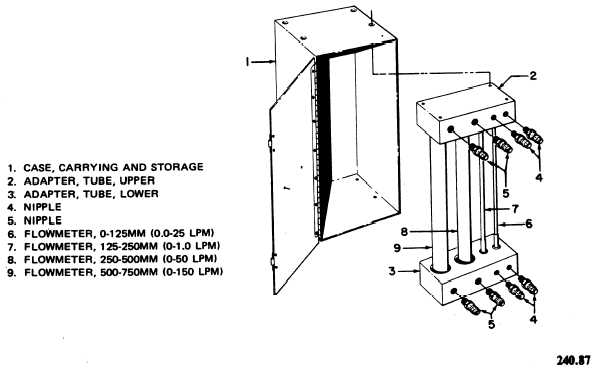
Figure 1-4. - Flowmeter Calibration Kit.
Continue Reading