4. Using applicable graphs, repeat steps 1 through 3 for all actual flows given on correction cards 4 through 7.
5. Indicated flows (in. H2 O) are entered on the cards when you calibrate the test stand.
Differential Pressure Gage (DF-1)
To prepare the differential pressure gage (DF-1) correction card, refer to figure 1-1 in the following steps:
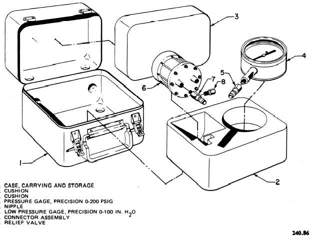
1. Close system bleed valve V-5 and open the oxygen supply cylinder valve. Connect precision-0-to-100-in. H2 O low-pressure gage 6 (figure 1-3) to bell jar bottom coupling C-1. Open differential pressure shutoff valve V-8.
NOTE: Correction cards will be completed at this time.
2. Slowly open oxygen supply valve V-6 until 100 in. H2O is indicated on the precision-0-to-100-in. H2 O low-pressure gage.
Compare this gage with the reading displayed on differential pressure gage DF-1.
3. Enter the difference (if any) in the indicated in. H2 O column of correction card number 1.
4. Slowly open system bleed valve V-5 to reduce the pressure indication on the precision-0-to-100-in. H2 O low-pressure gage. Reduce pressure in 20-in. H2 O increments. Enter the corrective differential (if any) at each interval on the correction card.
5. When all entries have been made on the correction card, close oxygen supply valve V-6 and differential pressure shutoff valve V-8.
6. Open system bleed valve V-5 and bleed the system. Disconnect the precision-0-to-100-in. H2 O low-pressure gage.
Test Pressure Gage (PG-1)
To prepare the test pressure gage (PG-1) cor- rection card, proceed as follows:
1. Connect precision-0-to-200-psig pressure gage 4 (figure 1-3) to bell jar bottom coupling C-1.

Figure 1-3. - Pressure Gage Calibration Kit.
Continue Reading