The components are so designed that when
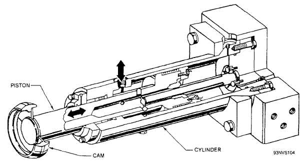
(fig. 4-42) operates the same as the advance stroke
operating in either direction, the piston starts slowly,
buffer and serves to stop the piston and crosshead
travels at maximum velocity throughout the greater
smoothly at the end of the retract stroke.
position of the stroke, and comes to a gradual stop.
The cylinder of the assembly is rigidly mounted on
Working along with the retraction engine cylinder
support brackets on the base of the retraction engine.
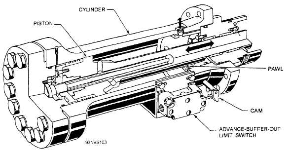
and piston are two buffers. The advance stroke buffer
The crosshead is mounted on the end of the piston,
is connected to the retract end of the retraction engine
which extends outside the cylinder.
cylinder by an adapter (fig. 4-41). Its purpose is to stop
the retraction engine piston and crosshead smoothly at
The flow of hydraulic fluid to
the end of the advance stroke. The retract stroke buffer
retraction engine cylinder for the C-7-
and from the
and C-11 -type
Figure 4-41.—Advance buffer.
Figure 4-42.—Retract buffer.
4-32