
ENGINE CONTROL QUADRANT
manually controls Ng and Np. In this mode, the
electrical control unit (ECU) is disabled. The only
An engine control quadrant is shown in
automatic function NOT de-energized is the Np
figure 7-9. It consists of two engine power
overspeed protection. To return to automatic
engine control, move the power lever to the IDLE
control levers, two engine fuel system selector
levers, and two engine emergency off T-handles.
position, then back to the FLY position.
It also has a power control lever rotor brake
interlock. Each power control lever has a starter
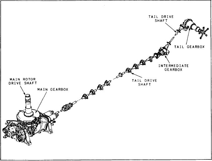
POWER TRANSMISSION SYSTEM
button and four selectable positions. The positions
The transmission system takes combined
are OFF, IDLE, FLY, and LOCKOUT.
power from two engines, reduces the rpm, and
Movement of the power control lever to the
transfers it to the main and tail rotors. The
OFF position moves a cable to shut off the fuel.
secondary function is to provide a drive for
Movement of the lever between IDLE and FLY
electrical and hydraulic power generation. The
sets the available gas generator turbine speed (Ng).
transmission system of a typical helicopter consists
Move the lever to the FLY position for flight rotor
of the main transmission gearbox, an intermediate
speeds. If demanded, this setting gives the highest
gearbox, a tail gearbox, and drive shafts. Most
available power. When moved to the LOCKOUT
systems also include an oil cooler, blower, and
rotor brake system. Figure 7-10 shows the SH-3
position momentarily, the power control lever
Figure 7-10.-SH-3 power transmission system.
7-13