
mount between the gas generator and power
inlet guide vanes and first two rows of stators are
turbines.
a variable geometry design.
Exhaust Section
Combustor Section
The exhaust section is aft of the turbine section
The combustor section houses an annular
and contains two power turbine speed (Np)
combustion liner. This section also contains
sensors. The exhaust section directs the hot
12 fuel injectors and 2 spark igniters.
exhaust gases to the atmosphere.
Turbine Section
PRIMARY HELICOPTER
The turbine section has four axial flow turbine
COMPONENTS
wheels. The first two wheels drive the compressor
and AGB. These turbines are known as the
Because components vary in function and
engine's gas generator turbines. The last two
complexity on different models of helicopters, we
wheels drive the main gearbox. These turbines
will discuss only representative units. Refer to the
are known as the engine's power turbines.
aircraft MIM for details on components for a
The turbine section also houses the seven turbine
specific helicopter.
gas temperature (TGT) thermocouples, which
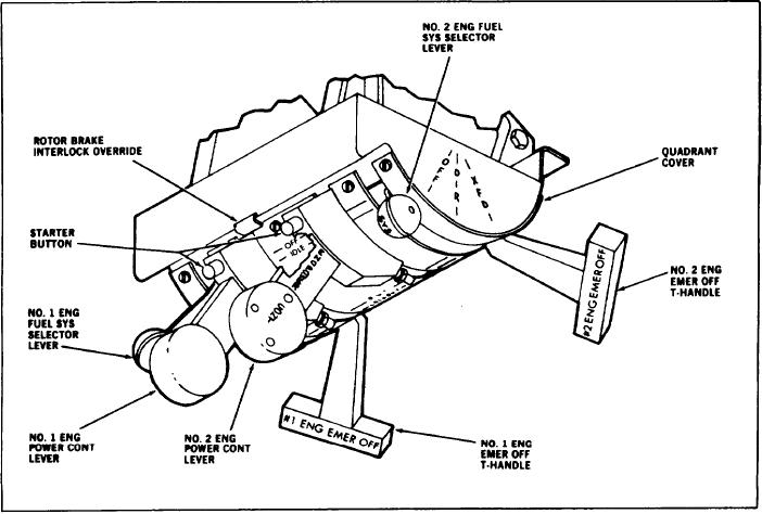
Figure 7-9.-Engine control quadrant.
7-12