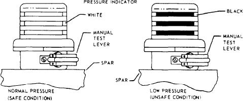
black that shows depends on pressure in the
blade has an air valve in the spar back wall near
s p a r . Remove from service any blade on
the root end and a cylindrical pressure plate. The
which the pressure indicator shows any black
root end plate is attached to the inboard end of
color. The blade may be put back into service
the spar. A seal plate is found inside the spar tip
when the unsafe (black) indication is found
end. Both are sealed for pressurization. Pressure
and corrected. Replace a malfunctioning in-
loss in the spar shows impaired integrity of the
dicator, but only if the spar pressure is within
spar or a seal leak. The cuff provides the means
permissible limits.
for attaching the blades to the rotary wing head
sleeve spindles. Nickel-plated or titanium abrasion
strips bonded to the spar leading edges prevent
erosion.
TAIL (ROTARY) RUDDER HEAD
Older blades consisted of a hollow extruded
The rotary rudder head provides for attach-
aluminum spar and aluminum pockets. They have
ment of the rotary rudder blades and counteracts
a tip cap, a root cap, and a steel cuff. Newer
the torque of the main rotor head. See figure 7-20.
blades consist of a pressurized titanium spar,
It also serves as a rudder for directional control
honeycomb core, and fiber glass graphite
of the helicopter. The rotary rudder head
skin. The newer blades are often repairable at
is driven by the tail gearbox. Blade pitch
organizational-level maintenance instead of depot
changes by the action of the pitch change
level. They are repairable at the lower level of
shaft. The pitch change shaft moves through
repair because of their honeycomb and fiberglass
design. Both types of blades are statically and
the center of the output gear shaft of the
tail gearbox. As the shaft moves outward
dynamically balanced to permit individual replace-
from the gearbox, the pitch of the blades
ment and interchangeability of the blades. In
decrease. The pitch beam is connected by
addition to balancing, manufacturers and depot
repair facilities stencil blades with a pretrack
adjustable pitch change links to the forked
number to aid in blade tracking.
brackets of the blade sleeves. The flapping
spindles permit flapping of the blades in each
direction.
The pressure indicator, usually known as
a BIM or a blade inspection method, compares
Tail rotor blades are built around a spar
built-in reference pressure with blade spar
that mounts on the tail rotor. The SH-3 has
pressure. See figure 7-19. When pressure
five all-metal, single aluminum pocket blades
in the spar is within the required service
bonded to a C-shaped spar. The SH-60 blades
limits, three white stripes show in the indicator.
are built around two graphite composite spars.
If pressure in the spar drops below the minimum
Honeycomb paddles are then bonded to the
permissible service pressure, the indicator will
spars with fiber glass to form the blade.
show three black stripes. The amount of
Figure 7-19.-Blade pressure indicator (BIM).
7-22

