
part. Figure 9-2 is a schematic diagram that shows
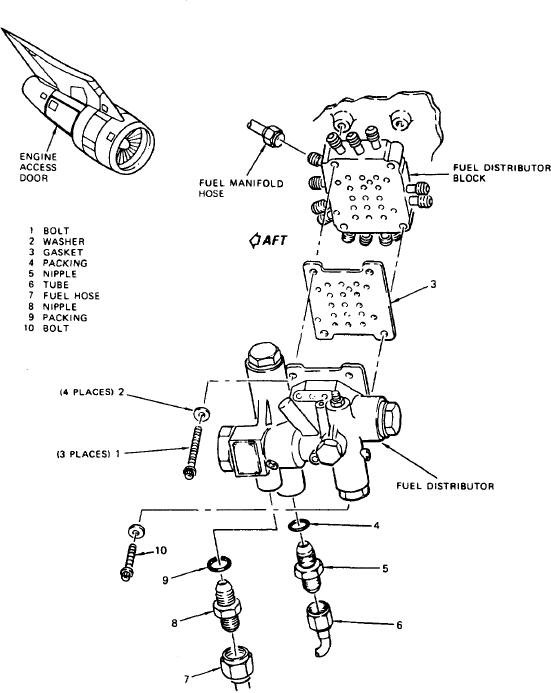
Pictorial diagrams show location, function,
the fuel flow of a turbojet engine fuel control.
and appearance of parts and assemblies. This
It shows the flow of fuel from the fuel pump
diagram is sometimes called an installation
through the fuel control, the fuel distributors, and
diagram. Pictorial diagrams are valuable for
the internal fuel tubes. Fuel from the internal fuel
locating and identifying parts. See figure 9-3.
tubes enters the combustion chambers through
Other uses for this type of drawing is the
fuel lines to the fuel manifold. Each part is
disassembled or exploded view and the cutaway.
illustrated and identified by name. The arrows
Cutaway drawings show the internal construction
show the direction of flow through each line and
of parts, and exploded views show how the
component within the fuel control.
various parts of a component are assembled.
Figure 9-3.-Pictorial diagram of a fuel distributor.
9-9