Tachometer
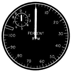
The tachometer (fig. 7-14) is an instrument for
showing the speed of the power section of a gas turbine
engine. A small alternator or generator attached to the
engine's
accessory
section
produces
a
voltage
proportional to the speed of the power section. This
voltage powers the pointer on the tachometer and
registers the percent of rpm being developed.
A dual tachometer is used in turbojet and
multiengine aircraft.
Fuel Quantity Indicator
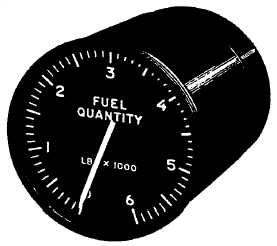
The fuel quantity indicator (fig. 7-15) is a
capacitor-type
gauge
system.
An
electronic
fuel-measuring device displays fuel quantity in pounds.
The dial of the indicator is calibrated from 0 to 6 (times
1,000) with line increments every 100 pounds.
Vertical Scale Indicator
On most new model naval aircraft, radial dial
indicators have been replaced by vertical scale
indicators. The vertical scale indicator is used to show
engine performance data, fuel flow, engine speed,
exhaust gas temperatures, and accelerometer readings.
Vertical scale indicators are compact, lightweight, and
easily read. Figure 7-16 shows a few examples of the
vertical scale indicators now in use.
GYROSCOPES
If not for using the properties of a spinning wheel,
precise navigation and instrument flying would be very
difficult. Two very important instruments that use the
properties of a gyroscope are the attitude indicator and
the turn and bank indicator.
Attitude Indicator
A pilot determines aircraft attitude by referring to
the horizon. Often, the horizon is not visible. When it is
dark, overcast, smoky, or dusty, you cannot see to use
the earth's horizon as a reference. When one or more of
these conditions exists, the pilot refers to the attitude
indicator. The attitude indicator is also known as a
vertical gyro indicator (VGI), artificial horizon, or gyro
horizon. Attitude indicators show the pilot the relative
position of the aircraft compared to the earth's horizon.
Attitude indicators may be different in size and
appearance, but they all have the same components and
present the same basic information. As shown in figure
7-17, a miniature aircraft represents the nose (pitch)
and wing (bank) attitude of the aircraft with respect to
the earth's horizon. A band on the face of the indicator
shows the degree of bank. The sphere is shaded light on
the upper half and dark on the lower half to show the
difference between sky and ground. The calibration
marks on the sphere show degrees of pitch. Each
indicator has a pitch trim adjustment so the pilot can
center the horizon as necessary.
7-10
ANF0714
Figure 7-14.—Tachometer, jet engine type.
ANF0715
Figure 7-15.—Fuel quantity indicator.