Figure 13-15.—Hot dimpling kit.
This same unit is used with both the hot dimpling
squeezer and the thermo dimple gun.
The hot dimpling squeezer is designed for use
where stationary squeezer operation is impractical or
impossible. It is capable of working all material
gauges up to and including 0.091 of an inch. The
squeezer is designed to dimple in areas that are
inaccessible to other types of equipment. Male and
female dies are independently warmed by electrical
heaters.
The heaters produce a short heat-up and
recovery time. The male die is adjustable to provide
the maximum squeeze on all gauges of material. The
unit also has a cooling feature.
The thermo dimple gun is used to dimple in the
center of panels and in those areas otherwise
inaccessible to stationary dimpling equipment. When
it is being used on the aircraft, the thermo dimple gun
drives the dimple from the exterior while the female
die and dolly bar are used on the inside. The thermo
dimple gun is air cooled. This eliminates the need for
cumbersome heat-resistant gloves. This tool is small,
compact, well balanced, and easy to handle.
Before adjusting the control unit for dimpling,
you should refer to the equipment manufacturer’s
dwell time chart. When you set up any dimpling
equipment, follow the step-by-step procedure
outlined in the operating and maintenance manual
supplied with the equipment. Since equipment types
vary, it is impractical to specify a standard procedure;
however, there are four general requirements of a
dimple, and by examining each, it is possible to
denote improper setting up of equipment.
1. Sharpness of definition. It is possible to get a
dimple with a sharp break from the surface into the
dimple. The sharpness of the break is controlled by
two things: the amount of pressure and the material
thickness.
2. Condition of dimple. The dimple must be
checked for cracks or flaws that might be caused by
damaged or dirty dies, or by improper heating.
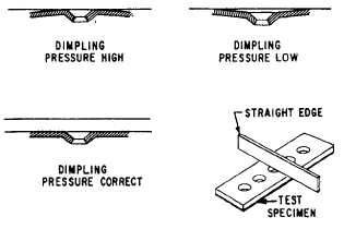
3. Warpage of material. The amount of warpage
may be held to a minimum if the correct pressure
setting is held. When dimpling a strip with too much
pressure, the strip tends to form a convex shape, as
shown in figure 13-16. When insufficient pressure is
used, it tends to form a concave shape. This can be
checked by using a straight edge.
Figure 13-16.—Checking dimple equipment air pressure.
13-11


