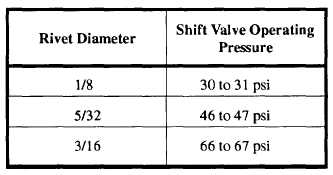
Table 13-3.—Adjustments for CP350 Blind Rivet Pull Tool
2. Press the trigger and release it the instant a
puff of exhaust indicates the shift valve controlling
the inner anvil has shifted. The gauge will then
indicate the shift pressure. See table 13-3 for the
approximate pressures.
NOTE: The trigger must be released
immediately as the valve shifts. Otherwise
the gauge will record the higher pressure that
builds up after the valve has shifted.
pressure is properly adjusted for the size rivets being
driven. Also make sure that the rivets are of proper
length. The tool has only one operating adjustment.
This adjustment is used to control the pull on the pin.
The desired amount of the pull depends on the
diameter of the rivets to be installed. The pull is
varied by changing the pressure at which the
adjustable shift valve operates. To adjust the
pressure, proceed as follows:
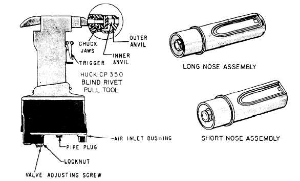
1. Remove the pipe plug from the tool cylinder
and connect a pressure gauge to the tool.
3. To adjust the pressure, loosen the valve-
adjusting screw locknut and turn the valve-adjusting
screw clockwise to increase pressure, or counter-
clockwise to decrease pressure, until the desired
pressure is obtained.
Check the pressure after
tightening the valve-adjusting screw locknut. When
you drive rivets of extremely long grip length, you
should make an adjustment to the high-pressure limit.
For efficient operation of the tool, the minimum
desired line pressure should be not less than 90 psi
and the maximum not more than 110 psi.
When you are using a CP350A or B rivet pull
tool, it may be necessary to increase the inside
diameter of the air inlet bushing, part number
81479, from 0.055 to 0.065 of an inch when you are
driving 3/16-inch-diameter rivets, if the line pressure
Figure 13-49.—Self-plugging rivet (mechanical lock) pull tool.
13-31