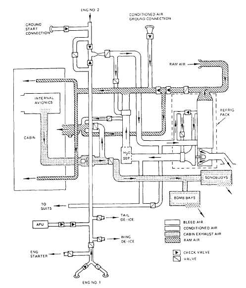
Figure 4-10.-ECS operation in aux vent mode.
System Components
Seven components are used to control cabin
temperature. These components are discussed in
the following paragraphs.
CABIN TEMPERATURE CONTROL MODU-
LATING VALVE.— The cabin temperature
control modulating valve has a visual position
indicator and is spring-loaded to the closed
position. It is located between the hot bleed-air
duct going to the refrigeration unit and the cooled
air duct coming from the refrigeration unit. The
cabin air temperature control provides electrical
power to a torque motor in the valve, which
converts electrical signals into pneumatic
signals that modulate the butterfly to a specific
opening.
CABIN AIR TEMPERATURE CONTROL.–
The cabin air temperature control, which is
located in the cabin inlet duct, senses duct
temperature with two thermistors and a control
circuit for signal comparison. The cabin air
temperature control output signal is in proportion
to the sensed temperature differential between the
inlet duct temperature and an input from the cabin
air temperature sensor. The output of the cabin
air temperature control, which goes through the
cabin air temperature selector, provides a
controlling signal for the cabin temperature
control valve.
4-16