controlled by three switches on the bleed-air
section of the ice protection panel. When the
solenoid is energized, it admits filtered, regulated,
bleed-air pressure to one side of a diaphragm
chamber in the valve. The other side of the
diaphragm chamber is spring-loaded to the closed
position. Movement of the diaphragm operates
a main line butterfly valve.
When the valve opens, hot air is admitted to
the leading edge distribution system. The hot air
goes through the modulator valve to the ejector
manifold, out the jet nozzles, and into the wing
leading edge plenum area. The bleed air is then
directed across a pneumatic thermostat. Increased
temperature across the thermostat actuates the
sensor and opens a bleed passage from the
diaphragm chamber. This reduces the pressure on
the diaphragm and allows a spring to close the
main valve.
THERMOSTATS.— The wing leading edge
pneumatic thermostat is installed adjacent to each
modulating valve. (See fig. 3-2.) The thermostat
controls air pressure on the modulating valve
diaphragm, and thereby controls the valve
opening.
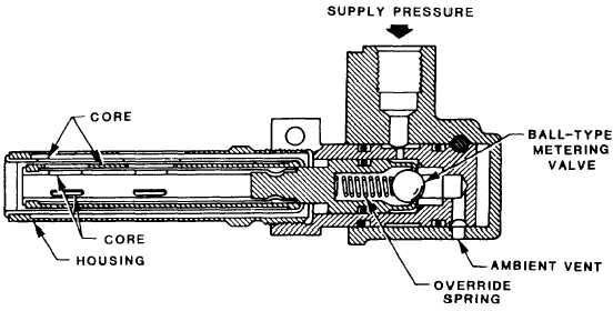
The unit is composed of a probe and a valve
assembly. (See fig. 3-3.) The probe is a core made
of layers of high- and low-expansion material that
is locked to a sliding piston. In addition, the piston
contains an override spring and ball-type metering
valve.
Airflow from the leading edge flows over the
core and causes the materials to expand or
contract. As temperature rises, the core pulls the
piston and metering ball from the seated position.
This allows pressure from the modulating valve
diaphragm to vent. Increasing temperature causes
more air to be bled from the diaphragm chamber.
Because of spring action, the modulating valve
moves toward the closed position. This restricts
flow through the modulator valve and drops the
skin temperature.
LEADING EDGE TEMPERATURE AND
OVERHEAT CIRCUIT.— To monitor the
overheat warning system, six skin temperature
sensors (one in the inboard section, one in the
center section, and one in the outboard section
of each wing) form a part of an amplifier circuit.
When the wing leading edge skin temperature rises
in excess of 230°F at any one or more sensors,
the airfoil temperature control unit amplifier
completes a caution light circuit, thus illuminating
the leading edge caution hot light.
Also, there are three ducting overheat thermal
switches installed in each wing and three installed
in the fuselage adjacent to the bleed-air duct.
These switches form a part of a loop that is
connected to a signal light control assembly.
When any one of the thermal leak detector
switches closes, its respective caution light
illuminates. Also, when the test switch is placed
in the TEST position, both lights illuminate
through their respective loop circuit.
The ducting overheat switches are single-pole,
single-throw, explosiveproof, thermally actuated
electrical switches with an integral temperature
Figure 3-3.-Wing leading edge thermostat.
3-4