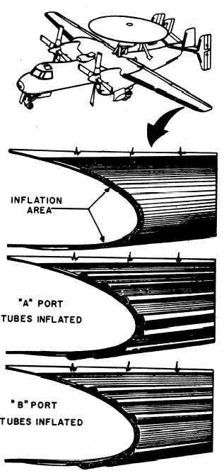
or tubes of the deice boots (fig. 1-7) are inflated
and deflated alternately by applying pressure and
suction, causing a wavelike motion that cracks the
formed ice and allows it to be carried away by
the airstream.
The E-2A deice boot system shown in
figure 1-8 is pneumatically operated and
electrically controlled. Engine bleed air provides
the necessary air pressure. The bleed air is
regulated by the pressure regulator and relief
valve. Suction is provided by the ejector and
regulated by the suction relief valve. Suction and
pressure gages provide a means of monitoring
system readings that indicate proper or improper
system operation.
The deice system consists of the follow-
ing main components: electronic timer, three
distributor valves, pressure regulator and relief
valve, ejector, suction relief valve, the de-
ice boot sections, and pressure and suction
gages.
ELECTRONIC TIMER.— A timer controls
the inflation and deflation of the deice boots by
alternately energizing and de-energizing the
solenoids of the distributor valves in a specific
sequence. Pressure and suction are applied to the
boots in the following sequence: the inboard wing
boots, the outboard wing boots, the outboard
stabilizer and vertical fin boots, and the inboard
stabilizer and fin boots.
Each group of boots is inflated for approx-
imately 5 seconds, and the succeeding group
begins inflating approximately 10 seconds after
the first group begins deflating. The total time for
the complete inflation cycle to all four boot groups
is approximately 1 minute. The timer is a sealed
unit and is maintained by personnel in the AE
rating.
DISTRIBUTOR VALVES.— Each of the
deice system’s three distributor valves (fig. 1-8)
has a pressure inlet port, a suction inlet port, two
outlet ports to the deice boots, and an exhaust
port. The exhaust port routes air returning to the
distribution valve in the deflation cycle overboard
to a low-pressure area. The low-pressure exhaust
area creates a slight suction to assist in deflation
of the boot. The pressure inlet port is connected
to the engine bleed-air manifold pressure line. The
Figure 1-7.—Deice boot location/operation.
suction port is connected to the main suction
line from the ejector. Approximately 4 in
Hg. suction is available at all times to the
distributor valves. Each distributor valve has
two solenoids that, when energized, allow air
pressure to inflate their respective boot tubes,
as was shown in figure 1-7. When the solenoids
are de-energized, the valves allow suction to
be applied to the boots, holding them down
(deflated) in flight.
1-8


