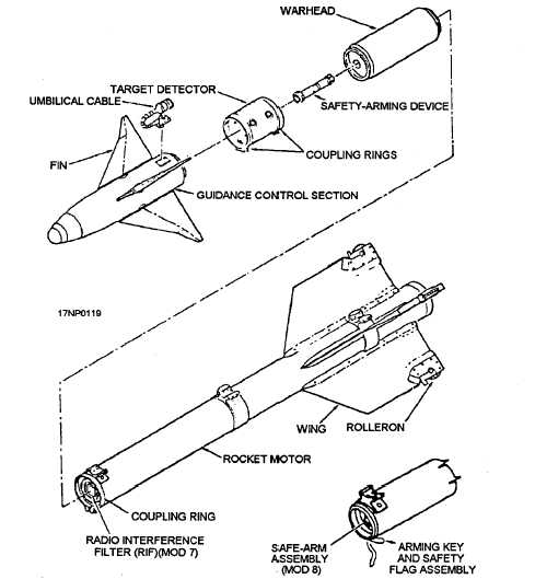
control section, the target detector section, the S&A
device, the warhead section, and the rocket motor
section (fig. 3-9).
The guidance and control section consists of the
following three major assemblies:
1. An infrared seeker assembly, which is used for
detecting the target.
2. An electronic assembly, which is used for
converting detected target information to tracking and
guidance command signals.
3. A gas servo assembly (which consists of a gas
generator, manifold, pistons, rocker arms, electrical
solenoids, and thermal battery), where the electrical
guidance commands are converted to mechanical
movement of the control fins.
Four BSU-32/B control fins are mounted on the
guidance and control section to provide aerodynamic lift
and course alterations to the missile during free flight.
They are movable surfaces that are electrically
controlled and pneumatically operated by the gas servo
assembly, The missile’s umbilical cable is also attached
to the guidance and control section. A shorting cap/dust
cover must be installed on the umbilical connector at all
times when the missile is not electrically connected to
the LAU-7 launcher. The umbilical cable provides the
necessary path for the exchange of electronic signals
between the missile and aircraft before missile launch.
It also provides a connection to the launcher-mounted
cooling gas supply, which prevents the electronic
components of the guidance and control section from
becoming overheated during operation before missile
launch. The umbilical cable is sheared off at missile
launch.
The target detector (TD) is a narrow-beam,
active-optical, proximity fuze system. The purpose of
the TD is to detect the presence of an air target within
the burst range of the missile warhead and generate an
electrical firing signal to the S&A device.
Figure 3-9.—AIM-9 series Sidewinders guided missile (exploded view).
3-12