Figure 5-29.-Image isocon target.
the method of extracting the video information from
the returned electron beam. The image isocon uses
scanning beam electrons scattered by the
positive-stored charges on the target. Figure 5-29
shows this method of signal generation.
When the primary scanning electron beam hits the
target, three events occur. Some of the electrons
neutralize the target, some electrons reflect back to
the gun, and some electrons scatter as they hit the
target. Instead of using the reflected electrons, the
image isocon uses the scattered electrons. These
electrons, as well as the reflected electrons, return
toward the electron gun. At the gun end of the tube,
the reflected electrons are separated from the
scattered electrons. The scattered electrons go to an
electron multiplier that amplifies the signals before
they are taken out of the tube.
The polarity of the signal developed by the isocon
is opposite to the polarity of the signal of the orthicon.
In the isocon, the maximum number of scattered
electrons occurs at the highlights of the picture, while
virtually no scattered electrons occur in the dark.
This produces a signal that has much less noise in the
lower lights. It also improves the ability of the tube to
handle a very wide range of light levels without
requiring additional camera adjustments.
The image isocon is useful in very low-light
applications where there is a wide range of scene
contrast. It is also useful where a low-noise signal is
important in low-light areas.
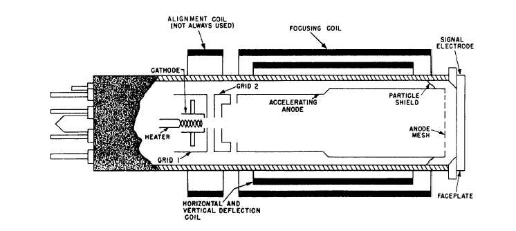
VIDICON.— The vidicon camera tube (fig. 5-30)
has a transparent conductive coating on the inner
surface of the faceplate. This coating is known as the
signal electrode. The signal electrode has a layer of
photoconductive material deposited on it. When light
from the scene being televised passes through the
faceplate and is focused on the photoconductive layer,
the resistivity of this material (which has been
extremely high) is reduced in proportion to the
amount of light reaching it. Because the potential
gradient between adjacent elements in the
photoconductive layer is much less than the potential
gradient between opposite sides of the layer, electrons
from the beam side of the layer leak by conduction to
electron beam.
Figure 5-30.-Structure of a vidicon tube.
5-24
the other side between scans of the