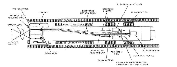
Figure 5-27.-Image orthicon tube.
each striking electron liberates several more electrons,
leaving a pattern of propottionate positive charges on the
front of the target. When the back of the target is scanned
by the beam from the electron gun in the base of the tube,
enough electrons are deposited at each point to neutralize
the positive charge. The rest of the beam returns to a
series of electron multiplier stages or dynodes
surrounding the gun.
Each dynode is a metallic disk with openings
similar to a pinwheel, and operates at a positive
potential of 200 to 300 volts greater than the
preceding dynode.
Multiplication occurs through
secondary emission at each dynode. If five dynode
stages are used, each having a gain of 4, a gain of
1,000 (4 x 4 x 4 x 4 x 4) is realized in the multi-
plier section. Now, consider dynodes with a gain of 5.
The overall gain would be 5,000. This setup would
allow the pickup tube to operate with relatively less
light than the plumbicon or vidicon (to be discussed
later). The electrons from the last dynode are routed
through a signal-developing resistor to an extremely
high B+ voltage. The output signal is then coupled to
the first stage of video amplification in the camera.
IMAGE ISOCON.— The image isocon tube
(fig. 5-28) is similar to the image orthicon in
construction and operation. The main difference is
Figure 5-28.-Image isocon tube.
5-23