The Sonar Detecting-Range Set AN/AQS-13E is
a lightweight, echo-ranging, dipping sonar set. It is
capable of detecting, tracking, and classifying moving
and stationary underwater objects. Also, this sonar
set provides capabilities for underwater voice
communication and generation of echo-ranging,
aspect, and bathythermographic recordings.
MAJOR COMPONENTS
The following text will discuss the various
components that makeup the AN/AQS-13E sonar
detecting-range set.
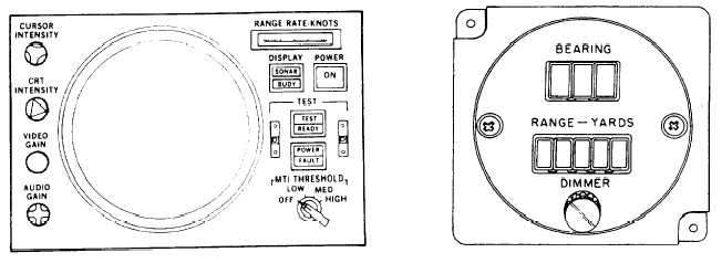
Azimuth and Range Indicator
The azimuth and range indicator (fig. 4-12) is
positioned at the sensor station. It provides the means
for the operator to track targets. There are four
controls on the left hand side of the indicator for
operator comfort. The CURSOR INTENSITY switch
controls the brightness of the cursor.
The CRT
INTENSITY controls the brightness of the overall
CRT. The VIDEO GAIN controls the level of the
video signal applied to the CRT. The AUDIO GAIN
switch controls the level of the audio signal.
The right side of the indicator face contains a
meter called the RANGE RATE-KNOTS meter. This
meter displays the opening or closing speed of the
selected target.
The MTI THRESHOLD switch
selects the range rate threshold of targets to be
displayed on the CRT. The DISPLAY switch selects
either sonobuoy signals or sonar signals to be shown
on the CRT. To activate the sonar set, press the
POWER switch. This activates the entire system with
the exception of the dome control. The TEST switch
initiates the built-in test functions and analyzes the
results.
Bearing and Range Indicator
The bearing and range indicator (fig. 4-13) is
mounted on the instrument panel, and presents the
pilot with target bearing and range information. This
information is supplied when the sonar operator sets
the receiver TARGET switch to VERIFY.
The bearing is displayed on a three-digit display
that shows degrees magnetic. The range is displayed
on a five-digit display that shows yards to target.
There is also a dimmer switch that controls the
intensity of the display illumination.
Cable Assembly and Reel
The special purpose cable is 500±5 feet long, and
is pretensioned on the reel. The cable contains 30
shielded conductors in a braided steel strength
member, and is protected by a waterproof outer
covering of polyurethane. There are colored bands
spaced along the length of the cable to aid in checking
the amount of cable payed out.
Dome Control
This control box (fig. 4-14) allows the operator to
raise and lower the transducer (dome). There are
three switches and two indicators on the face of this
control box. The DEPTH-FEET indicator advises the
operator on how far the transducer is lowered in feet.
Figure 4-12.-Azimuth and range indicator.
Figure 4-13.-Bearing and range indicator.
4-10