
The output from the directional gyro is routed to the
particles in the transmission system and main engine
CSEP, where the signal is amplified and conditioned.
sumps.
The CSEP output is routed to the rate of turn indicator
mounted on the operator console.
APU FEED Section
The auxiliary power unit (APU) FEED section
OUTSIDE AIR TEMPERATURE SYSTEM
contains the switches that control the port and starboard
APU coalescer drains. The sump chip detector alarm
The outside air temperature system provides an
circuitry can be turned on and off from this section.
indication of the outside ambient air temperature for
Switches are also provided to bring 400-Hz power from
display on the AMS flight data display page. The
the aft switchboards to the forward power panels.
temperature probe is mounted on the outside of the
Located to the left of the C&C keyboard are
personnel and equipment module forward bulkhead. An
switches and knobs that control panel illuminations (not
illustration of the outside air temperature probe is shown
shown). A push-button switch is provided to test the
in figure 7-14.
AMS and C&C keyboard lighting.
SPEED/SIDESLIP INDICATOR
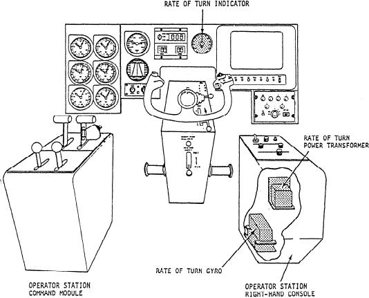
RATE OF TURN SYSTEM
The speed and sideslip indication is generated by
The function of the rate of turn system is to provide
the high-speed velocity log (HSVL). The HSVL system
an indication in degrees of the craft's rate of turn. The
develops craft speed and sideslip (drift) angle data
components of the LCAC rate of turn system are shown
relative to the surface on which the craft is traveling.
in the shaded portions of figure 7-13. The system
This information is provided to the data converter unit
consists of a rate of turn directional gyro, an indicator,
(DCU) where it is checked against calibration curves
and a power transformer. The 400-Hz power panel or
designed to reflect terrain characteristics. The output
command module 400-Hz load center provides power
from the DCU is sent to the engineer AMS display and
Figure 7-13.--Rate of turn gyro system.
7-13