
provide isolation, switching, and distribution.
normal to alternate if the normal source fails.
These components include ABTs, MBTs, and
Power is fed through an ABT to most of the vital
transformers. This equipment routes power from
equipment on board ship. The normal and
the SWBD to the loads. Some equipment protects
alternate sources of power for an ABT are fed
the distribution system from casualties in the
from two independent sources of power. They are
loads; other equipment transforms and switches
never fed by two sources from the same SWBD.
the power to send it to the load. In the following
Figure 9-16 is a line diagram of a typical vital
sections, we will discuss these components and the
circuit from the SWBD to the load. Lighting in
protective features they add to the entire distribu-
vital areas are also fed via ABTs.
tion system.
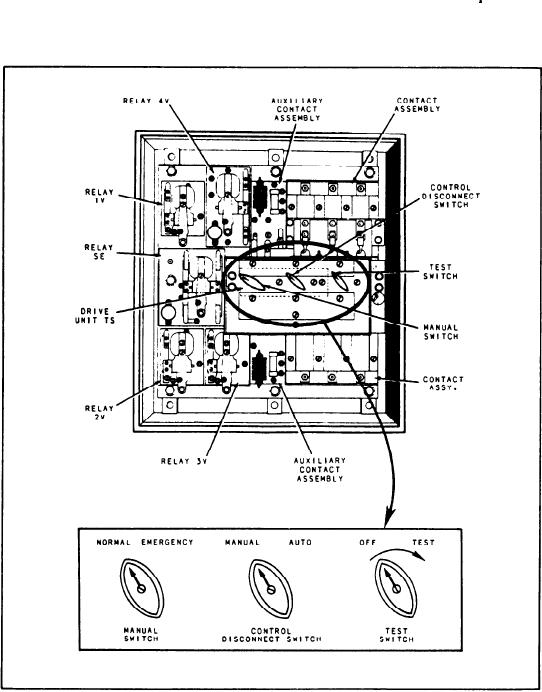
The model A-2 ABT unit is designed to handle
Automatic Bus Transfers
small loads. It operates on 120-volt, 60-Hz circuits. This
unit (fig. 9-17) may be used on single- or 3-phase
An ABT is an electromechanical device that
circuits. For purposes of explanation, the 3-phase
automatically switches power sources from
unit will be discussed.
Figure 9-17.--A pictorial view of an ABT.
9-17