in fractional horsepower sizes in commercial and
domestic applications. The advantages of using
single-phase motors in small sizes are that they
are less expensive to manufacture than other
types, and they eliminate the need for 3-phase ac
lines. Single-phase motors are used in electronic
equipment, fans, refrigerators, portable drills,
grinders, and so forth.
A single-phase induction motor with only one
set of stator windings and a cage rotor is similar
to the 3-phase induction motor with a cage rotor.
The single-phase motor has no revolving magnetic
field at start; therefore, no starting torque.
However, the rotor can be brought up to speed
by special design of the stator winding. Then the
induced currents in the rotor will cooperate with
the stator currents to produce a revolving field.
This causes the rotor to continue to run in the start
direction.
The identification of single-phase motors is
determined by the different methods starting
torque is provided. These methods are split-phase,
capacitor, or universal.
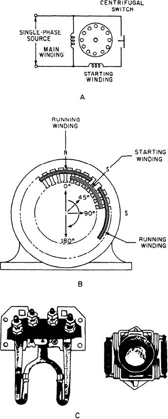
SPLIT-PHASE MOTOR.--The split-phase
motor (fig. 9-4) has a stator composed of slotted
laminations. The stator has an auxiliary (starting)
winding and a running (main) winding (fig. 9-4,
view A). The axes of these two windings are
displaced by an angle of 90 electrical degrees. The
starting winding has fewer turns and smaller wire
than the running winding; hence, the starting
winding has higher resistance and less reactance.
The main winding occupies the lower half of the
slots. The starting winding occupies the upper half
(fig. 9-4, view B). The two windings are connected
in parallel across the single-phase line that
supplies the motor. The motor gets its name from
the action of the stator during the starting period.
At start, these two windings produce a
magnetic revolving field. This rotating field
rotates around the stator at synchronous speed.
As it moves around the stator, it cuts across the
rotor conductors and induces a voltage in them.
This voltage is maximum in the area of highest
field intensity. Therefore, it is in phase with the
stator field. The rotor current lags the rotor
voltage at start by an angle that approaches 90
degrees because of the high rotor reactance. The
interaction of the rotor currents and the stator
field causes the rotor to accelerate in the direction
in which the stator field is rotating. During
Figure 9-4.-- Split-phase motor. A. Circuit diagram. B. Wind-
acceleration, the rotor voltage, current, and
ing configuration. C. Centrifugal switch.
reactance are reduced. The rotor currents come
closer to an inphase relation with the stator field.
9-5

