
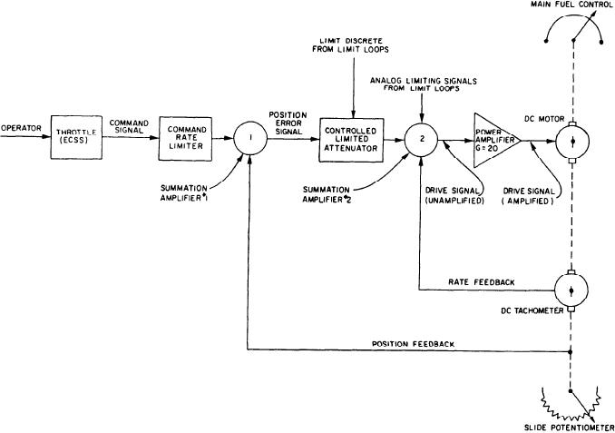
Figure 2-58.--Gas turbine simplified control loops.
voltage. If that voltage is exceeded, the speed
of the PLA actuator's drive signal and inserts a
limiting circuit goes into action to limit the PT
fixed voltage to drive the MFC to idle.
speed or acceleration.
If the command signal exceeds a maximum
of +12 volts dc or falls below a minimum of +0.3
ACCELERATION LIMIT CONTROL.--A
volt dc, a command loss condition exists. Both
separate circuit also receives the PT speed signal
the fail-to-idle relay energizing voltage and the
where the rate of speed change (acceleration) is
system fail signal are generated.
monitored. If the acceleration exceeds 332
A malfunction is considered to exist if the
rpm/second, this circuit lowers the PLA actuator
unamplified drive signal to the rotary actuator
drive signal to lower the PT acceleration.
exceeds +2.7 volts or below 2.7 volts for
1 second or longer. Again both the fail-to-idle
PLA COMMAND RATE LIMIT CON-
relay energizing voltage and the system fail signal
are generated.
TROL.--The position of the MFC lever is
proportionally'controlled by the command signal.
If the MFC is at idle and an overtorque
The rate of change of the lever position is
condition exists or if either of the 15-volt power
normally limited to predetermined increasing and
supplies fail, a system fail signal is generated.
decreasing rates by the command rate limiter.
SYSTEM FAIL PROTECTION.--The PLA
PLA Actuator Theory of Operation
actuator generates two signals when certain
abnormal conditions are detected. One is an
In the following discussion, please refer to
uplink signal to indicate a system failure; the other
figure 2-58 to help you trace the command signal
energizes the fail-to-idle relay to open the path
from the throttle to the MFC.
2-55