Four-way Control Valve (Stack Valve)
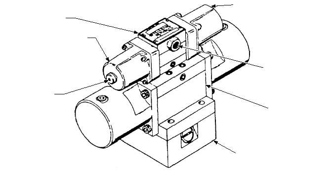
A four-way control valve (stack valve) (fig. 5-7)
controls the flow of hydraulic fluid to and from a pair of
hydraulic cylinders. The stack valve is a solenoid
controlled, pilot-operated valve assembly. The stack
valve consists of a solenoid-operated valve, a
pilot-operated main valve, and a sequence valve. All
three valves are secured together to conserve space and
simplify connection to a subplate or manifold. One
stack valve controls fluid flow for a pair of panel
assemblies. Three stack valves are required for Mk 7
Mod 0/2 and two stack valves for Mk 7 Mod 1 JBDs.
Hydraulic fluid at 2,500 psi from the associated
catapult is supplied to the stack valve with all fluid
return lines going to that catapult gravity tank. The
operation of a stack valve is described as follows:
1.
With hydraulic fluid at normal operating
pressure and neither solenoid B (raise) nor
solenoid A (lower) energized, fluid flows
through the sequence valve and pilot valve to
both sides of the slide in the main valve. This
pressure to both sides of the slide keeps it
centered and blocks fluid flow into and out of
both ends of the hydraulic cylinders.
2.
When a raise switch is actuated, solenoid B in
the pilot valve energizes, shifting the spool and
directing pressure to a pilot port at the main
valve side. The slide shifts and directs fluid to
port A of both hydraulic cylinders. The
hydraulic cylinder pistons extend, pushing the
crank assembly of the operating gear aft and
rotating the shaft. Rotation of the shaft extends
the operating gear linkage and raises the
associated panel assemblies. During the raise
cycle, fluid in the cylinder lower port B vents to
the gravity tank through the main valve. If the
raise switch is released during the raise cycle,
solenoid B deenergizes, a spring returns the
solenoid spool to the centered position, and
panel movement will stop. Fluid flow will be as
described above in step a.
3.
When a lower switch is actuated, solenoid A in
the pilot valve energizes, shifting the spool and
directing pressure to a pilot port at the main
valve slide. The slide shifts in the opposite
(from raising) direction and directs fluid to port
B of both hydraulic cylinders. The pistons
retract, pulling the crank assembly of the
operating gear forward and rotating the shaft.
The rotation of the shaft retracts the operating
gear linkage and lowers the panels. During the
lower cycle, fluid in the raise port A vents to
the gravity tank through the main valve. . If the
lower switch is released during the lower cycle,
solenoid A deenergizes, a spring returns the
5-7
SOLENOID-OPERATED
PILOT VALVE
SOLENOID B
MANUAL PUSH PIN
(BOTH ENDS)
SOLENOID A
THREADED FITTING
FOR CONDUIT
CONNECTION
PILOT-OPERATED
MAIN VALVE
SEQUENCE
VALVE
ABEf0507
Figure 5-7.—Four-way control valve.