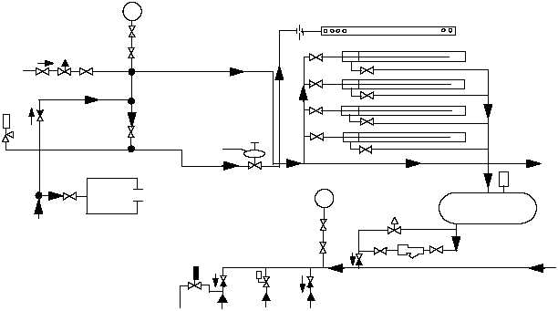
accumulator warm-up, steam is available through a
branch line and valves to the trough warm-up system
(fig. 4-3). The launching engine cylinders are heated to
operating temperature by a pair of trough heaters
located below each row of launching engine cylinders.
The rough heaters are installed in two sections referred
to as the forward and aft legs. Each trough heater
consists of a pipe within a larger pipe that is capped at
the forward end. Steam is admitted into the inner pipe,
them flows through the inner pipe into the outer pipe,
heating the outer pipe. Fins installed on the outer pipe
provide even radiation of heat to the launching engine
cylinders, condensation from each outlet pipe is
removed by drains lines which are equipped with fixed
orifices. The orifices are sized so that water is removed
at a rate that will maintain enough steam flow to heat
and maintain the launching engine cylinders at
operating temperature, bypass valves are provided
around each orifice to remove excess water if required.
STEAM SMOTHERING SYSTEM
The steam smothering system (see fig. 4-3)
provides a rapid means of extinguishing a fire in the
catapult trough or in the launch valve compartment.
The launch valve steam smothering is accomplished by
admitting steam into a pair of lines encircling the
launch valve area, holes in these lines direct steam to
cover the area.
Trough steam smothering is accomplished by
admitting main steam into a pipe located between the
launching engine cylinders, holes in the pipe direct
seam to all of the trough area. Trough steam smothering
can be actuated pneumatically by a valve at deckedge or
manually
by
a
bypass
valve
located
near
the
pneumatically operated steam supply valve.
WET ACCUMULATOR OPERATION
The steam accumulator provides a volume of steam
under pressure to the launch valve assembly. At
operating temperatures, when the launch valve opens
and steam is released to the launch engine cylinders,
steam pressure within the accumulator drops, when the
pressure drop in the accumulator occurs, the steam fill
valve open and admit steam into the accumulator by
means of a perforated manifold submerged in the water,
this will rapidly heat the water back to the operating
temperature. Water level will return its pre-established
level.
LAUNCHING ENGINE SYSTEM
LEARNING OBJECTIVES: Describe the
components of the launching engine system.
Describe the function of the launching engine
system.
4-3
ABEf0404
CAT
STEAM
SUPPLY
COMPT
STEAM
SMOTHER
CONSTANT STEAM
HEATING SUPPLY
CAT DK
EDGE STA
RESERVOIR
NOT ON ALL
INSTALLATIONS
THROUGH HEAT
FINNED PIPES
(AFT LEGS)
TO FWD
LEGS
FROM FWD
LEGS
STEAM SMOTHERING
PIPING
ORIFICE
TO SERVICE
STM DRAIN
DISCH OVBD
TO ATMO
TO HP
DRAINS
Figure 4-3.—Trough heat and steam smothering.


