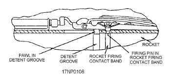
(fig. 2-18). When the rocket is loaded and unloaded, a
detent lift tool is used to raise and lower the detent pawl
by rotating the detent lift handle, which is located at the
forward end of the launcher. The detent also supports
the firing pin. Each firing pin (fig. 2-18) is part of the
detent assembly and is raised and lowered concurrent
with the pawl. The firing pin extends into the tube and
contacts the rocket firing contact band, which is located
aft of the rocket detent groove.
When the switch in the aircraft firing circuit is
closed, electrical current flows from the aircraft firing
circuit through the electrical receptacle, safety switch,
mode selector switch, intervalometer, and the firing pin
in the launcher to the contact band in the forward end of
the motor, and through the lead wire to the squib in the
igniter. The current entering the rocket squib heats the
squib primer mixture, which, in turn, ignites the igniter
charge.
Pressure within the igniter unseats a blowout plug,
permitting the burning charge to ignite the propellant
grain. The whole process of ignition requires about
0.005 second. Pressure of the hot propellant gases from
the burning grain bursts the nozzle seal and provides the
thrust to propel the rocket. Thrust overrides the detent
spring, releasing the pawl from the rocket detent
groove. The thrust then pushes the rocket out the
forward end of the tube. The impact from the first
rocket out shatters the forward fairing and the blast
removes the tail fairing.
2.75-INCH (SERIES) LAUNCHERS
The 2.75-inch (series) launchers are intended for
shipping (in some cases, with warheads installed)
stowing, and firing the 2.75-inch rockets. The weight of
loaded launchers varies, depending upon the number of
rockets installed and rocket configuration.
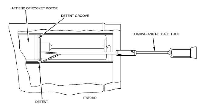
The rockets are retained in the launcher tubes
during shipping, handling, and flight by engagement of
a leaf-spring type of detent with integral blast paddles
(fig. 2-19). During loading, the rocket motor depresses
the detent until the detent snaps into the detent grooves
located on the aft end of the motor. To remove rocket
motors, use a rocket loading and release tool to depress
2-18
Figure 2-18.—LAU-10 (series) detent pin and firing pin
assembly.
Figure 2-19.—Rocket launcher detent (2.75-inch).