5. The motor contact bands, motor tube threads,
and nozzle and fin assembly must be clean and
free of grease or other lubricants.
6.
Check threads for damage or corrosion.
Assembly of Rocket Components
Rocket components are assembled as discussed in
the following steps:
WARNING
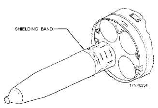
Ensure launcher is grounded. Shielding
bands must be in place whenever the rocket
motor is out of or protrudes from the
launcher. Ensure the shielding band covers
the contact band but does not touch it.
1.
Place detent lift arm in load position.
2.
Push forward on aft end of rocket motor until
forward end of rocket emerges from launcher.
3.
Slide shielding band (fig. 13-23) over motor
and hold against forward part of launcher; push
motor forward until locking tabs seat in the
motor detent grooves and not in the contact
band groove.
NOTE: A standard rocket assembly tool kit
containing
crowfoot
wrenches,
a
torque
wrench,
detent
locking
wrenches,
chain
wrenches, and strap wrenches is available for
the assembly of 2.75-inch and 5.0-inch rockets.
4.
Hold motor with strap wrench. Screw warhead
into motor and tighten securely with chain
wrench until the warhead seats 360 degrees.
5.
Attach appropriate nose fuze and tighten.
6.
Push rocket motor slowly into the tube until aft
end contacts aft stop.
7.
Rotate detent lift arm to flare position.
8.
Push the motor forward hard; pawl will engage
groove with audible click indicating positive
engagement.
2.75-INCH AIRBORNE ROCKET ASSEMBLY
PROCEDURES
Unpacking and inspection of the warhead, fuzes,
and motor are essentially the same as for the 5.0-inch
rocket components discussed earlier in this chapter.
Assemble rocket components as follows:
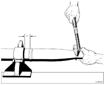
1.
Place rocket motor body in holding fixture (fig.
13-24).
13-23
Figure 13-23.—5.0-inch rocket RADHAZ and electrostatic
protection.
Figure 13-24.—Holding fixture assembly.