installed in the aircraft, one on each side of the fuselage
and one on the centerline on the fuselage bottom.
Search Store System
The search store system has the necessary
equipment and accessories to carry and release
sonobuoys. Also, the sono system can carry and release
several other search-related stores.
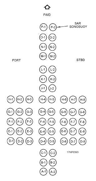
Part of the search store system consists of
unpressurized size A sonobuoy launch tubes (SLTs).
These are installed in the underside of the aircraft
fuselage.
There are 60 SLTs.
The SLTs are not
accessible from the pressurized aircraft cabin (flight
station); therefore, the designation "unpressurized."
The SLTs may be reloaded only from the outside of the
aircraft.
Look at figure 15-34.
It shows the
arrangement of the SLTs as you look up at the lower
fuselage.
Bomb Bay System
The bomb bay system consists of the units and
components needed to carry, arm, and release stores.
The bomb racks are attached to brackets mounted to the
aircraft in a cruciform pattern.
Each of these basic
installations is assigned a station number. Numbers
followed by a letter (such as A or B) designate these
stations for special capacities or types of stores. These
stations are arranged in pairs, such as stations 1 and 2, 3
and 4, etc.
For ground maintenance without power on the S-3,
you need to use a 3/8-inch drive crank to open or close
the doors. Both aircraft have a ground safety pin to
disable the door mechanism in the open position. The
door safety pin must be inserted when you are
working in the bomb bays.
The release of bomb bay stores is normally
accomplished by the computer, as programmed by the
TACO and controlled by the TACO with copilot
backup. The pilots have final control because they must
activate the master arm switch.
S-3 Configurations
The S-3 bomb bay suspension has two BRU-14/A
bomb racks. The racks are suspended from the bomb
bay overhead support braces. Arranging the racks in
various locations on the support braces makes different
configurations. Figure 15-35 shows the configurations
available for each bomb bay.
The basic configuration of the S-3 consists of dual
stations—stations 1 and 2 and stations 3 and 4 across
the bays. The station A configuration consists of dual
tandem stations in each bay—1A and 2A, 3A and 4A.
These two configurations are used, as necessary, to
provide store clearance, depending on the shape and
size of the store. The single store configuration consists
of one station per bay—1B and 4B. This configuration
is used for special purposes, such as special weapons.
The BRU-14/A rack is held in position by two
mounting bolts through the forward mount. Mounting
pins secured to the aircraft braces restrain the rear of the
rack assembly. Electrical receptacles at each mounting
position provide connection for the rack to the aircraft
circuits.
15-29
Figure 15-34.—S-3 sonobuoy launch tube arrangement.