Rigging
To adjust the steering amplifier, proceed as follows:
1. Insert rigging pin No. 1 in rudder pedal
Rigging of the control linkages consists of several
linkage, and check to see that rudder is in neutral.
steps. You must jack the nose of the aircraft and operate
the rudder pedals to deplete hydraulic pressure. Center
2. Operate the steering switch and check to see
the recoil strut manually so that the link arm is in line
that gear centers within 2 degrees of center index mark.
with the centers of the strut and the steering assembly.
3. If gear does not center within limits, adjust the
Adjust all lower links to move freely overcenter, to
steering amplifier potentiometer R7 so that the circuit
make sure that parts are free from binding, and then
balances.
lock in place with the stops. Install rigging pins in the
4. Remove rigging pin and check the area for
rudder pedal to nose steering assembly linkages.
foreign objects.
Adjust the rods to accommodate the installation of
the pins. Following adjustment of the linkage, remove
5. Remove the jack and external power.
the rigging pins and check the system for proper
NOTE: AE personnel normally accomplish the
operation.
electrical adjustments.
Steering Assembly Maintenance
MECHANICALLY CONTROLLED NOSE
STEERING SYSTEM MAINTENANCE
O-rings, packings, and miscellaneous parts within
the steering assembly can be replaced at the
Maintenance of mechanically controlled nose
intermediate level of maintenance. Trouble analysis
steering systems closely parallels the maintenance
charts are in many of the MIM and 03 manuals. The
of electrically controlled nose steering systems.
charts accommodate the systematic checkout of
Mechanically controlled nose steering system mainte-
individual components. Like the aircraft trouble-
nance consists of the rigging and steering assembly
shooting charts, they are based on manufacturer's
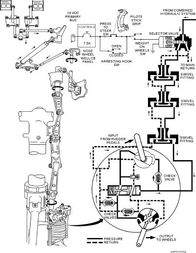
maintenance. See figure 15-4.
experience, past part discrepancies, and part design.
Figure 15-4.--Nosewheel steering system.
15-5

