electrical fail-safe system operates and de-energizes
same time, the actuator operates the cable drum
the selector valve to close the speed brakes. If the
mechanism. The cable drum mechanism operates the
synchronizing linkage becomes jammed, the torsional
jack screw mechanism to reposition the follow-up trim
bungee assembly can be forced out of detent, isolating
tab to aerodynamically maintain the aileron surface in
the linkage from the speed brake and preventing
a position corresponding to that achieved by the
damage to the linkage because of overloads.
hydraulic actuation.
The bungee in the synchronizing mechanism
The tab movement does not control the lateral trim
linkage acts as a rigid length to the synchronizing valve
of the aircraft while normal powered flight is
during normal operation of the wingtip speed brake. If
maintained. This is accomplished by the
the valve becomes jammed, abnormal loads on the
hydraulic-powered displacement of the ailerons.
bungee will cause it to give and relieve the excessive
When the manual flight control system is used, the
loads before damage to the valve, linkage, or bungee
follow-up trim tab position introduced during powered
occurs.
operation becomes effective and maintains the same
trim as that provided by the powered operation.
TRIM SYSTEM
With the power system disconnected, further
hydraulic trim control ends, and all future trim inputs
A trim system is provided in the flight controls to
are achieved through aerodynamic effect. This
lessen the need for constant effort on the part of the
function depends upon selective follow-up tab
pilot to maintain the desired heading and altitude. The
position. Engaging the AFCS controls the trim
trim system stabilizes the aircraft during flight.
actuator by electrical inputs.
Lateral Trim
Aircraft without trim tabs achieve lateral trim by
repositioning the lateral control surfaces as necessary
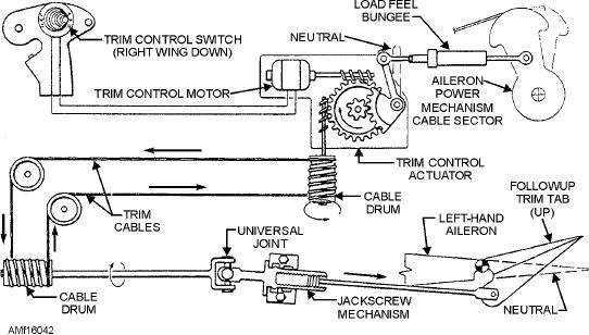
The aileron trim control system is shown in figure
to achieve a balanced lateral flight condition. The trim
16-42. The illustration represents a trim tab
actuator, located in the aileron trim and mixing
arrangement similar to that found on aircraft equipped
linkage, normally acts as a series-connected,
with conventional aileron systems.
fixed-length rod in the aileron control system. The trim
control switch on the stick grip controls the actuator
Operation of the lateral and longitudinal trim
length. Shortening or retracting the trim actuator (trim
systems is usually controlled by a five-position,
button to the right) supplies a left wing up input into the
four-throw, momentary ON contact switch with a
aileron control system linkage. Extending the actuator
center OFF position. The switch is found on the control
supplies a left wing down input. The trim actuator
stick grip. This switch electrically energizes the trim
changes the neutral position of the aileron mechanism,
control motor, which operates the trim control actuator
allowing the control surfaces to deflect and trim the
to reposition the load-feel bungee and achieve
hydraulic-powered actuation of the ailerons. At the
aircraft without moving the control stick.
Figure 16-42.--Aileron trim control system.
16-47

