
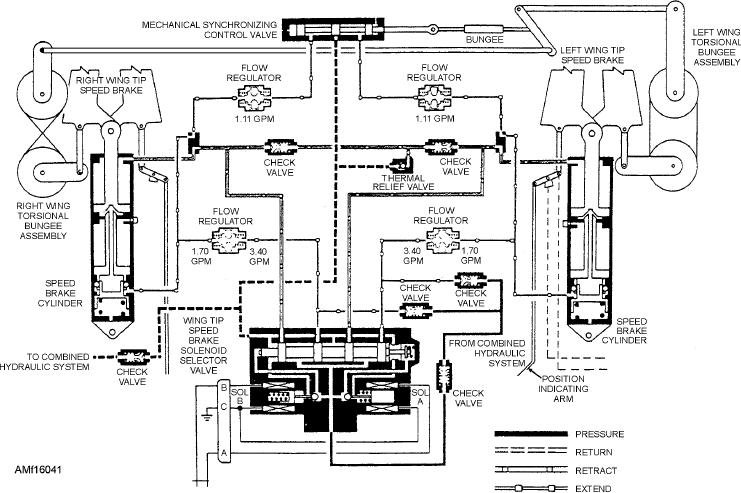
Figure 16-41.--Wingtip speed brake control system.
brakes. The switch is spring-loaded to neutral from the
On some aircraft, the synchronization mechanism
(fig. 16-41) consists basically of synchronizing
aft position only.
linkage, two torsional bungee assemblies, and a cable
Selecting the open position energizes the selector
run interconnecting the three mechanisms to a
valve, porting hydraulic pressure from the combined
m e c h a n i c a l s y n c h r o n i z i n g c o n t r o l va l ve . T h e
hydraulic system to the extended side of the actuating
synchronizing mechanism is a comparative linkage
cylinder. When the switch is positioned to closed, the
type that senses unequal motion between the two brake
opposite solenoid energizes. Pressure is ported to the
surfaces. Movement of either speed brake transmits
retract side of the actuating cylinders. With the switch
through the torsional bungee assembly and the cables
in neutral, hydraulic fluid is blocked from both the
to the synchronizing mechanism. Any unequal
movement upsets the synchronizing mechanism's
extend and retract sides of the speed brake cylinders.
neutral position, displacing the synchronizing valve
This action hydraulically locks the speed brakes. If
shuttle. When the speed brakes are opening or closing,
the electrical circuit fails, the selector valve is
the valve is normally in neutral as long as the travel of
de-energized as a fail-safe feature and the speed brakes
both sides is equal. When unequal travel moves the
retracts.
valve shuttle out of neutral, the valve will relieve
The wingtip speed brake control system normally
hydraulic pressure from the speed brake actuating
depends upon the hydraulic flow regulators to maintain
cylinder, producing the largest opening angle. This
symmetrical extension of the left and right brakes. If a
decelerates the opening of the speed brake or bleeds
down the speed brake with the largest angle until the
malfunction causes asymmetry of extension, an
disparity is within limits and the shuttle returns to
electrical disparity signal is sensed by the speed brake
neutral. On later models this mechanical
null detector. When the disparity between the
synchronization system has been deleted.
extension of the left and right brake reaches 8 degrees,
the null detector de-energizes the selector valves and
If the mechanical synchronization system fails to
causes the speed brakes to close.
maintain synchronization within 8 degrees, the
16-46