
Placing t h e f l a p c o n t r o l h a n d l e t o L A N D
mechanically closes the 40-degree down flap handle
switch. The electrical circuit to the selector valve
completes, this time through the now closed 40-degree
down limit switch in the flap drive gearbox. The flaps
will extend to 40 degrees, and the electrical circuit will
be broken by the action of the limit switch.
Moving the flap control handle to the TAKEOFF
or UP position will energize the opposite solenoid of
the flap selector valve and port pressure to the retract
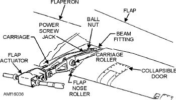
Figure 16-36.--Flap actuator.
side of the flap hydraulic motor. If the TAKEOFF
also reduce the flap drive gearbox speed of 1,080 rpm
position is selected, a limit switch will again halt flap
to about 550 rpm at the outboard actuators.
movement at the 30-degree position. If UP is selected,
retraction will be halted when the flaps reach the full up
FLAP WING-FOLD SHAFT.--A wing-fold
position. Stopping the flaps is a function of the flaps up
shaft consists of two interlocking splined sections and
limit switch. At the same time, linkage from the up
two universal joints connected to quill shafts. It
limit switch actuates a second switch to complete the
provides a telescoping fold joint in the flap drive
electrical circuit to the flap hydraulic motor brake
system linkage between the inboard and outboard wing
valve. The energized valve blocks combined hydraulic
panels.
system pressure that is holding the hydraulic brake in
the unlocked position. The brake locks the hydraulic
Slat System
motor, which, in turn, locks the flaps in the up position.
The slat system, shown in figure 16-37, provides
If combined hydraulic system pressure fails and
additional lift and stability to the aircraft at lower
the emergency flap switch is used, the flap action is
speeds in the same manner as the leading edge flap
powered by the electric motor. See figure 16-35. The
system previously discussed. The flap control handle
flap hydraulic brake valve is energized, and the
controls the movement of the slats. Moving the flap
pressure holding the spring-loaded hydraulic motor
control handle to the TAKEOFF or LAND position
brake unlocked will port to return. The brake is then
causes the slats to extend to a 27.5-degree leading edge
free to lock the motor and input shaft.
down position.
The electric motor now drives the flap gearbox and
The slat panels, one inboard and one outboard,
associated linkage, bypassing the locked hydraulic
interlock by a pin when the wings are spread. When
motor. This action occurs until the flaps reach a
fully retracted, the slats align with the top and bottom
40-degree trailing edge down position. Limit switches
wing contours to form the wing leading edge. Shim
shut the electric motor off when the flaps reach the
spacers between the slats and the slat tracks provide
40-degree down and full up positions.
adjustment for proper aerodynamic fairing.
FLAP ACTUATOR.--The flap actuator shifts
Components of the slat system are similar to those
rotary motion of the input shaft to linear flap motion,
in the flap system. The slats extend and retract by using
using bevel gears and the ball screw jack mechanism.
six series-linked ball screw actuators. The actuators are
See figure 16-36. A load-sensing device in each flap
powered by the hydraulic motor through gearboxes
actuator operates a clutch assembly to stall out the flap
and torque tubes.
system if it is overloaded. An impact plate at the end of
the ball screw (screw jack shaft) and mechanical stops
If combined hydraulic system pressure fails, the
on the actuator body protect the actuator against
hydraulic motor is locked in the same manner as the
p o s s i b l e ove r t r ave l d u r i n g f l a p ex t e n s i o n a n d
flap hydraulic motor, permitting the emergency
retraction.
electric motor to move the slats. Emergency slat
operation is accomplished simultaneously with
OFFSET GEARBOXES.--The eight offset
emergency flap operation, using the emergency flap
gearboxes in the flap system transmit power produced
switch. Slat position is also displayed on the cockpit
by the flap drive gearbox around wing structure
obstacles and compensate for wing angularity. They
integrated position indicator.
16-41