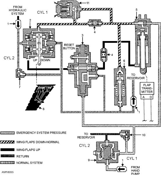
1.
Check valve
5.
Wing flap cylinder
9. Wing flap emergency selector valve
2.
Wing flap selectro valve
6.
Wing flap blowup relief valve
10. Relief valve
3.
Wing flap emergency dump valve
7.
Wing flap thermal relief valve
11. Wing flap snap shutoff valve
4.
Restrictor
8.
Wing flap control
Figure 16-33.--Wing flap system.
The cylinder is double acting and internally locked
the flaps and flap linkage. This valve is adjustable to a
in the retracted (flaps up) position. The cylinder also
narrow range between full flow and reseat, providing a
has an integral shuttle valve (built into the mounting
controlled blowup feature. As the flaps blow up, the
end cap). This provides for the separation between the
flap air load decreases, gradually reseating the relief
normal and emergency hydraulic pressure lines. An
valve and preventing further flap retraction.
adjustable terminal on the piston rod provides for
In the landing configuration, the flaps are partially
length variation.
or fully down. Safety microswitches prevent folding of
When the cylinder extends, the internal lock is
the wings until the flaps are in the full up position. To
hydraulically released, allowing the piston to move.
reduce the recovery interval aboard ship, the aircraft
When the flaps raise, the hydraulic pressure on the lock
wings must be folded and the aircraft taxied forward as
is relieved, and a compression spring engages the lock
quickly as possible. A wing flap retraction shutoff
mechanism with the piston when the cylinder becomes
valve installed in the flap down line expedites flap
fully retracted.
retraction. This normally closed, solenoid-operated,
hydraulic shutoff valve energizes only when the
A relief valve installed in the normal flap down line
weight of the aircraft is on the wheels. When
provides a blowup feature that prevents overloading of
16-37

