
pivoting at its lower end and moving the selector valve
The flap system discussed in this section is a
representative system. The number of flaps will vary
lever to the left. This action directs pressure from the
according to the size of the aircraft. The components
hydraulic system to the flap actuating cylinder (1). The
m a y h ave d i ff e r e n t n a m e s , d e p e n d i n g o n t h e
cylinder piston rod extends and lowers the flaps by
manufacturer, but the operational theory remains the
rotating the flap drive bell crank (3) in a clockwise
same. This system consists of a series of six flaps, three
direction. As the bell crank moves, the lower end of the
on the trailing edge of each wing. They raise and lower
floating arm moves to the right by the spring-loaded
in the conventional manner by a hydraulically actuated
pushrod (7). This action pivots the arm at its upper
linkage of bell cranks, pushrods, and idlers. The flap
connection to the sector pushrod and returns the
control lever in the cockpit controls the system
selector valve to neutral, stopping the action of the
mechanically. The lever connects by conventional and
system.
teleflex cables to the hydraulic actuating mechanism.
An emergency system is provided for lowering the
Moving the flap handle upward reverses the
flaps by operating a hand pump if the primary system
foregoing procedure by pushing the selector valve
malfunctions. The flap system has a position indicator
lever to the right, directing hydraulic pressure to the
and several safety devices to prevent lowering of the
retract side of the cylinder piston and raising the flaps.
flaps while the wings are folded, or folding of the
The follow-up rod then moves the lower end of the
wings while the flaps are lowered.
floating arm to the left and returns the selector valve to
neutral. The valve will not return completely to neutral,
The movement of the flap selector lever in the
maintaining pressure in the flap cylinder and ensuring
cockpit sets the flaps in motion. Movement of the
selector lever operates a cable quadrant to which a set
positive locking of the flaps in the up position.
of conventional control cables attach. These cables
The spring mechanism in the follow-up rod
connect to another sector just forward of the main wing
normally does not function. The spring mechanism is
beam. A teleflex cable, also attached to this aft sector,
provided only as a safety feature, permitting actuation
and a spring-loaded pushrod on the main flap actuating
of the flap drive crank by emergency hydraulic power if
bell crank connect to the two ends of a short floating
the selector valve becomes jammed.
arm installed on the hydraulic selector valve lever.
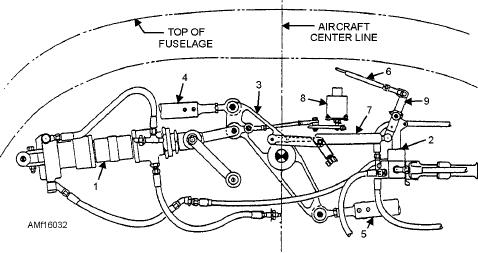
Figure 16-32 is a drawing of the cylinder, linkage, and
The flap hydraulic system consists primarily of the
selector valve installation. Reference to the index
selector valve and the actuating cylinder. See figure
numbers on this drawing is made in the following
16-33. The selector valve is a four-way, poppet-type
description of the operation of the flap control system.
valve. The poppets operate in pairs to direct pressure to
one side of the cylinder while opening the other side to
When the flap handle in the cockpit moves down,
reservoir return.
the upper end of the floating arm (9) pulls to the left,
1. Wing flap cylinder
4. Left flap contro pushrod
7. Follow-up pushrod
2. Wing flaps selector valve
5. Right flap control pushrod
8. Flap position transmitter
3. Flap actuating bell crank
6. Flap control push-pull cable assembly
9. Selector valve floating arm assembly
Figure 16-32.--Flap cylinder, linkage, and selector valve installation.
16-36