
names. On one aircraft, it is called a unit horizontal tail
the utility hydraulic system. The other valve is
(UHT) control system. On another aircraft, it is called
supplied hydraulic pressure by the flight control
the stabilizer control system. Regardless of the
hydraulic system. The power cylinder has dual
variation in nomenclature, these systems function to
hydraulic chambers to work from each control valve.
control the aircraft pitch about its lateral axis.
Each hydraulic system simultaneously supplies
3,000-psi hydraulic pressure to the power mechanism.
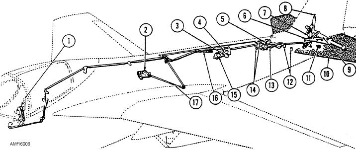
The horizontal stabilizer control system shown in
If one hydraulic systems fails, the other system
figure 16-6 is representative of an S-3 aircraft. The
supplies enough pressure to operate the mechanism. If
slab-type stabilizer responds to fore-and-aft manual
both hydraulic systems fail, the cylinder disconnects
input at the control stick. It responds to automatic
by pulling the MAN FLT CONT (manual flight
flight control system electrical signals introduced at
control) handle in the cockpit. The controls work
the stabilizer actuator.
manually through the linkage of the mechanism to
Pilot signals are conveyed through bell cranks and
operate the elevators.
pushrods and a trim mechanism to the input linkage of
The load-feel bungee, shown in figure 16-5,
the stabilizer actuator. A trim switch on the control
provides an artificial feel to the control stick. The
stick grip provides a means of setting stabilizer trim.
bungee acts as a centering device for the elevator
Stabilizer trim deflection is from -6 down to +1 up.
system. Control stick movement compresses the spring
Stabilizer trim is displayed by the stabilizer trim
in the bungee. Releasing the control stick causes the
indicator located on the pilot's lower instrument panel.
compressed spring to return the stick to neutral. The
See figure 16-7.
bungee also adds a gearing effect between the
horizontal stabilizer and the elevators. When the
The position of the stabilizer is shown on the
stabilizer is trimmed to give an aircraft nose up
integrated position indicator located on the left side of
condition, the bungee action adds nose up elevator.
the pilot's instrument panel. When the stabilizer is in
With the stabilizer trimmed nose down, the bungee
the "clean" configuration, the STAB window of the
action adds nose down attitude on the elevator.
indicator shows the word CLEAN. When the stabilizer
is in the "dirty" configuration, the window shows a
Horizontal Stabilizer Control System (Single
picture of a stabilizer.
Axis)
The stabilizer actuator (fig. 16-7) is a tandem-
Various aircraft manufacturers identify the
type actuator powered by both flight and combined
system pressures. It contains a power valve shuttle, two
horizontal stabilizer control system by different
1.
Control stick
7.
Load-relief bungee
13.
Negative bobweight
2.
Flap drive gearbox
8.
Stabilizer actuator
14.
Clean and dirty switches
3.
Trim transmitter
9.
Stabilizer support shaft
15.
Electrical trim actuator
4.
Artificial feel bungee
10.
Stabilizer
16.
Static spring
5.
Stabilizer shaft mechanism
11.
Stabilizer position transducer
17.
Stabilizer shift mechanism cables
6.
Walking beam
12.
Filters
Figure 16-6.--Stabilizer control system.
16-5