
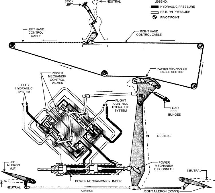
Figure 16-8.--Hydraulically powered aileron control system.
through a latch mechanism, operates the power crank.
bungee operating the power mechanism, which
The crank moves the push-pull tubes, which actuate
repositions the aileron control system to a new neutral
the ailerons. In the event of complete hydraulic power
position.
failure, a handle in the cockpit may be pulled to
In normal operation of the control system, when
disconnect the latch mechanisms from the cylinder.
the control stick is actuated left or right, the power
When the handle is pulled, it places this particular
mechanism compresses the bungee. The compressed
aileron system in complete manual operation. In
bungee returns the stick to the neutral position upon
manual operation, the power cylinder is disconnected
release of the stick.
from the cable sector, causing the control stick to
manually move the ailerons at a reduced rate.
Flaperon Control System
The lateral control system incorporates a load-feel
The flaperon control system, shown in figure
bungee, which serves a dual purpose. See figure 16-9.
16-10, is an example of lateral control provided by an
The bungee provides an artificial feel and centering
electrohydraulic-mechanical flaperon system. The
device for the aileron system. It is interconnected
system includes an inboard and outboard flaperon for
between the aileron system and the aileron trim
system. Energizing the aileron trim actuator moves the
each wing and three actuators (a single flaperon
16-9