
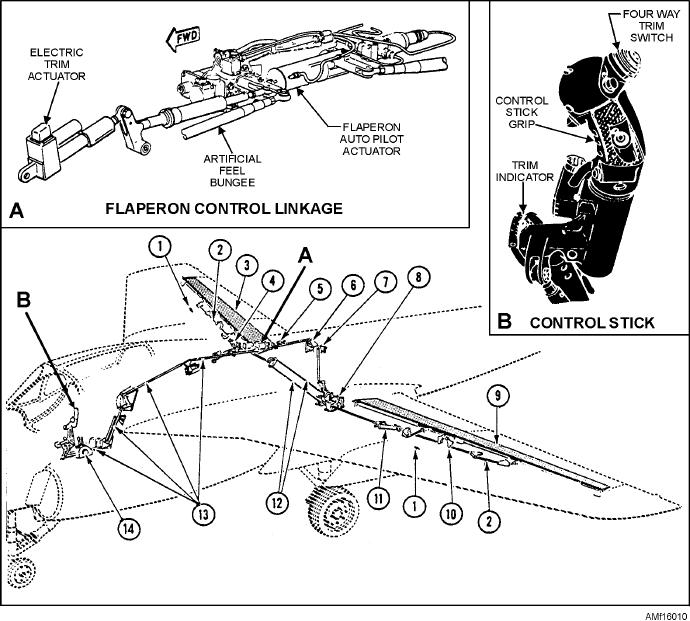
1.
Wing-fold flaperon interlock switch
8.
Flaperon pop-up mechanism and cylinder
2.
Flaperon control linkage
9.
Left wing flaperons
3.
Right wing flaperons
10.
Flaperon control linkage
4.
Flaperon actuator (right wing)
11.
Flaperon actuator (left wing)
5.
Flaperon pop-up valve
12.
Crossover cables
6.
Wing-fold interlock mechanism
13.
Pushrods
7.
Filter
14.
Throttle quadrant
Figure 16-10.--Flaperon control system.
powered by the combined and flight hydraulic
AUTOPILOT ACTUATOR.--The flaperon
autopilot actuator (figs. 16-12 and 16-13) contains an
systems. They are capable of operating on only one
electrohydraulic servo valve, actuator pistons,
system if one system should fail.
solenoid valve, transducer, series link, and series-link
The artificial-feel bungee provides an initial
rod. It indirectly controls flaperon movement in
control stick preload and increased force feel over the
response to mechanical movements from the pilot. It
full range of stick displacement. The
receives electrical inputs from the automatic flight
electromechanical actuator provides lateral trim,
control system. The actuator can operate in two
modes--manual or series.
which varies the neutral position of the artificial-feel
bungee. Trim is set by the switch on the control stick
I n m a n u a l m o d e , t h e s o l e n o i d va l ve i s
grip. The pilot may read the mechanical flaperon trim
de-energized and no fluid is ported to any part of the
indicator on the control stick.
actuator. The actuator piston rod is free to idle. The
16-11