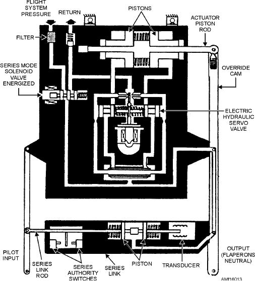
Figure 16-13.--Flaperon autopilot actuator.
series-link cylinder acts as a rigid link that transfers
SYSTEM ACTUATORS.--The flaperon system
input lever motion to the output lever.
actuators directly control the flaperon movement in
response to mechanical movement from the autopilot
In series mode, the solenoid valve energizes and
actuator. The actuator (fig. 16-12) consists of two
ports pressure to the servo valve. Pressure from the
tandem-mounted power pistons and a power valve
servo valve drives the actuator pistons together. This
shuttle. Mechanical inputs are introduced through the
pressure causes the pistons and the rod to act as one
load-relief (safety) bungee and the valve input lever to
piece. When the servo valve is at null, pressures in the
the power valve shuttle portion of the actuator. The
piston end chambers are equal. Electrical signals from
inputs cause a valve error and the porting of hydraulic
the automatic flight control system cause the
pressure to the power pistons. As the flaperon moves,
electrohydraulic servo valve to differ the pressures in
mechanical linkage attached to the actuator tends to
the end chambers. The signal provides the working
null this valve error. The power valve shuttle returns to
force for the actuator. The actuator piston rod drives
neutral. The flaperons remain in the selected position
the output lever. Pressure at the series link compresses
until new mechanical inputs are received from the pilot
a lock spring, unlocking the series link. The actuator
or the AFCS.
can stroke the pilot-commanded piston. When the pilot
moves the input link, relative motion between input
Combination Aileron/Spoiler Deflector System
and output causes the transducer to send a signal to the
AFCS amplifier. The signal combines with other flight
Navy aircraft employ more than one system for
stability signals, and the resultant signal operates the
lateral control of the aircraft. Figure 16-14 shows an
servo valve. The AFCS can be overridden by the pilot
aileron and spoiler/deflector arrangement to achieve
an increased roll rate about the longitudinal axis.
applying a stick force of 25 pounds.
16-13

