
Auxiliary Servo Cylinder
Mixing Unit
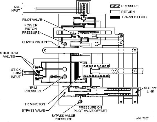
This cylinder consists of four separate banks of
The mixing unit consists of a system of bell cranks
and linkage. The unit coordinates and transfers
servomechanisms constructed as a unit. Figure 17-7
independent movements of the lateral, forward, aft,
shows the fore-and-aft bank of the servo cylinder. The
and directional controls. Movement is sent to the
other banks are similar in design and operation.
primary servo cylinders and the rotary rudder. The
The hydraulic power pistons of each bank help
mixing unit also integrates collective pitch control
flight control movements before the movement is sent
movements with those of the lateral, fore-and-aft, and
to the mixing unit. The cylinder operates on
directional systems. It causes the controls to move the
mechanical input during manual operation of the flight
three primary servo cylinders simultaneously in the
controls. The cylinder operates on electrical input
same direction. It changes the pitch on the rotary
rudder blades to compensate for the change in pitch of
from the ASE, and on electrical input from the stick
the rotary-wing blades.
trim system.
Each of the four banks operates in a single area of
Primary Servo Cylinders
control functioning, providing fore-and-aft, lateral,
collective, and directional hydraulic aid. Each bank
These three servo cylinders send flight control
has a mechanical and electrical input hydraulic servo
movements to the stationary swashplate of the
rotary-wing head. If the primary hydraulic system is
valve capable of displacing the pilot valve shuttle for
operating, the servo cylinders hydraulically aid flight
ASE operation. Additionally, the fore-and-aft and the
control movement. If the power fails, they function
lateral banks have a pair of solenoid-operated stick
only as control rods. See figure 17-8. This is
trim valves. These valves control fore, aft, and lateral
accomplished by the spring-loaded bypass valve,
movements through the stick trim system.
which prevents hydraulic lock and a sloppy link pilot
The directional bank uses a pedal damping piston
valve connection. The pilot valve and the lower clevis
that restricts sudden heading changes. The auxiliary
of the power piston connect to the flight control linkage
servo cylinder operates at 1,500-psi hydraulic pressure
by the same bolt. There is a very close tolerance in the
supplied by the auxiliary hydraulic system.
pilot valve connection. This tolerance causes the pilot
Figure 17-7.--Auxiliary servo cylinder.
17-8