
AIRCRAFT ELECTRICAL HARDWARE
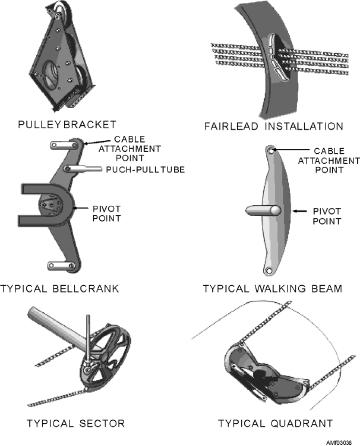
See figure 3-38. Besides holding the pulley in the
correct position and at the correct angle, the brackets
LEARNING OBJECTIVE: Recognize the
prevent the cable from slipping out of the groove on the
different types of common electrical hardware
pulley wheel.
used on naval aircraft.
SECTORS AND QUADRANTS
An important part of aircraft electrical maintenance
is determining the correct type of electrical hardware
These units are generally constructed in the form of
for a given job. These maintenance functions normally
an arc or in a complete circular form. They are grooved
require a joint effort on the part of the AM and the
around the outer circumference to receive the cable, as
AE/AT personnel. You must become familiar with wire
shown in figure 3-38. The names sector and quadrant
and cable, connectors, terminals, and bonding and
are used interchangeably. Sectors and quadrants are
bonding devices.
similar to bell cranks and walking beams, which are
used for the same purpose in rigid control systems.
WIRE AND CABLE
Q3-24.
Where space is limited, what type of fitting is
For purposes of electrical installations, a wire is
used to connect a cable to a quadrant?
described as a stranded conductor covered with an
Q3-25.
A turnbuckle barrel with internal left-hand
insulating material. The term cable, as used in aircraft
threads can be identified by what means?
electrical installations, includes the following:
Two or more insulated conductors contained in
Q3-26.
What is the total thread tolerance for a
turnbuckle assembly?
the same jacket (multiconductor cable)
Q3-27.
What type of cable guide should be used for a
Two or more insulated conductors twisted
small opening where a single cable passes
together (twisted pair)
through a wall separating unpressurized
One or more insulated conductors covered with
compartments?
a metallic braided shield (shielded cable)
A single insulated conductor with a metallic
braided outer conductor (RF cable)
For wire replacement work, the aircraft mainte-
nance instruction manual (MIM) should be consulted
first. The manual normally lists the wire used in a given
aircraft.
CONNECTORS
Connectors are devices attached to the ends of
cables and sets of wires to make them easier to connect
and disconnect. Each connector consists of a plug
assembly and a receptacle assembly. The two
assemblies are coupled by means of a coupling nut.
Each consists of an aluminum shell containing an
insulating insert that holds the current-carrying
contacts. The plug is usually attached to the cable end,
and is the part of the connector on which the coupling
nut is mounted. The receptacle is the half of the
connector to which the plug is connected. It is usually
mounted on a part of the equipment. One type of
connector commonly used in aircraft electrical systems
Figure 3-38.--Control system components.
is shown in figure 3-39.
3-22