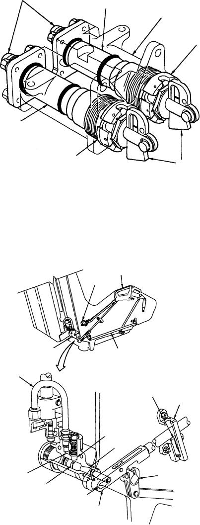
CONNECTORS
IMPULSE CARTRIDGE
BODY
LH FIRING MECHANISM
IMPULSE CARTRIDGE CCU-105/A
RH FIRING MECHANISM
SEARS
Figure 2-27.--Seat initiator.
EJECTION SEQUENCE
When the ejection control handle is pulled, the
sears are withdrawn from the seat initiator firing
On firing of the impulse cartridges, gas from the
mechanisms (fig. 2-27) and the two impulse
RH and LH cartridges is routed as described.
cartridges are fired, catapulting the seat free of the
RH Initiator Cartridge
aircraft and starting the sequencer modes for
seat/occupant separation and parachute deploy-
Gas from the RH cartridge is piped as follows:
ment.
1. To the pin puller (fig. 2-28), which withdraws a
piston from engagement in the lower operating
HANDLE
FIRING
MECHANISM
PIN PULLER
LEG RESTRAINT LINE
OPERATING LINK
GAS PIPE FROM
SEAT INITIATOR
SPRING-LOADED
PLUNGER
GUIDE BRACKET
PLUNGER
PISTON
CROSS-SHAFT
GAS PASSAGE
PISTON GROOVE
SLOT
OPERATING TANK
Figure 2-28.--Emergency restraint release system (SJU-17(V)1/A, 2/A, and 9/A).
2-25

