tube acting between the breech groove and the
TOP LATCH MECHANISM
wedge-shaped end of the plunger.
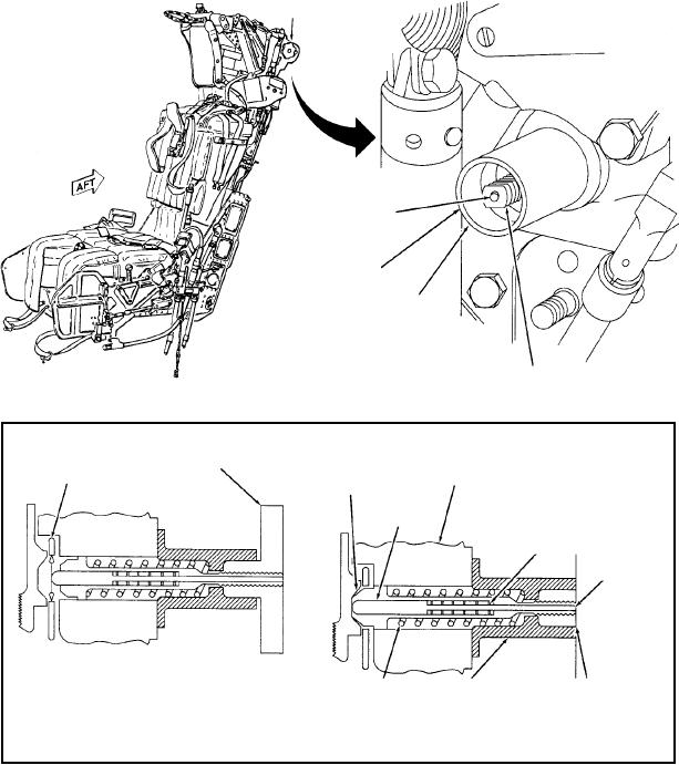
The top latch mechanism (fig. 1-7), on the upper
A spring-loaded dowel indicator in the top latch
left side of the top cross-member and main beam
plunger extends beyond the wedge-shaped end of the
assembly, locks the three ejection tubes and main beam
plunger to ensure that the plunger is completely
assembly together, securing the seat in the aircraft.
bottomed in the inner piston tube breech groove. The
Locking is done by a spring-loaded plunger that
dowel indicator is the same length as the top latch
protrudes through the left main beam, the ejection gun
plunger. When the plunger is completely bottomed in
outer cylinder barrel safety latch, and the housing, its
the inner piston tube breech groove, the indicator is
wedge-shaped end protruding into the inner piston tube
forced back against the spring and its outboard end is
breech locking groove. Before removing the seat from
flush with the end of the plunger. If the latch is not
the aircraft, the plunger must be mechanically
completely bottomed in the breech groove, the plunger
withdrawn by screwing a handwheel onto the plunger.
extends beyond the plunger housing and the dowel
On ejection, the top latch plunger is withdrawn by
indicator is recessed within the plunger.
forces from the initial movement of the inner piston
HANDWHEEL
DOWEL
INDICATOR
PLUNGER
HOUSING
A
PLUNGER
TOP LATCH MECHANISM
EJECTION GUN
HANDWHEEL
CYLINDER BARREL
MAIN BEAM
INNER POSITION
SAFETY LATCH
ASSEMBLY
LOCKING GROOVE
TOP LATCH
PLUNGER
DOWEL
INDICATOR
SPRING
DOWEL
INDICATOR
SEAT UNLOCKED WITH
TOP LATCH
TOP LATCH
TOP LATCH PLUNGER
SPRING
HOUSING
TOP LATCH DISENGAGED
FLUSH WITH HOUSING-
DOWEL INDICATOR FLUSH
WITH PLUNGER
SEAT LOCKED WITH
TOP LATCH ENGAGED
A
AMEf0107
Figure 1-7.--Top latch mechanism.
1-10

