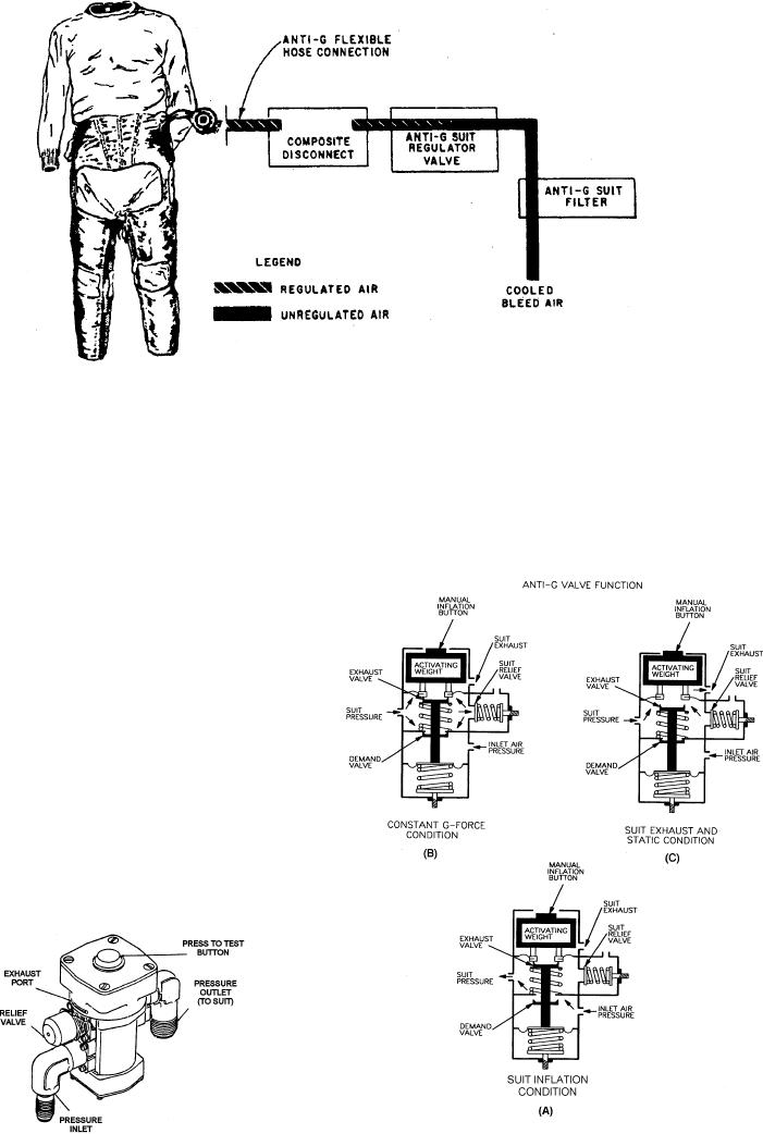
Figure 5-12.--Anti-g system.
relief valve relieves excessive suit pressure and
Most anti-g systems are similar to the one
maintains pressure at a maximum of 11 psi.
illustrated in figure 5-12. This system consists of a
supply line, an air filter, a pressure regulating valve, a
When a force of approximately 1.5 g's is exerted on
connecting hose, and a suit attachment fitting (single
the aircraft, the activating weight overcomes the upper
quick-disconnect or composite quick-disconnect). The
spring tension and closes the exhaust valve (fig. 5-14,
air pressure used in this system may be taken directly
from the engine compressor bleed air ducting, but is
usually taken off the air-conditioning ducting
downstream from the heat exchanger.
COMPONENTS
Components of the anti-g system include a valve, a
system filter, and quick-disconnects.
Anti-g Valve
The anti-g valve (fig. 5-13) is automatically
controlled by any positive or negative g-force. The
anti-g valve receives air from the high-pressure bleed
system and regulates it to a maximum of 10 psi for
delivery to the g-suit. The anti-g valve incorporates an
internal demand, exhaust, and relief valve. The internal
Figure 5-14.--Anti-g valve operation.
Figure 5-13.--Anti-g pressure regulating valve.
5-13

