
DV
L a JG E
N cd
ABC
X
b
Z
ef
P FH K MW
R
S
TU
J1
S3
F1
START
S1
S5
ON OFF
S4
12
L1
S6
3
12
+
L2
K24
S7
3
K25
12
K22
K23
L3
3
S2
12
L4
C A B D J7
S8
3
CA
12
L5
B
D
3
S9
M3
+
T1
12
L6
3
S10
12
L7
3
K26
K27
S11
12
L8
M4
+
3
12
L9
K9
K1
3
K10
K2
K11
K3
K12
K4
K28
K29
M5
K13
K5
+
K14
K6
K15
K7
K18
K8
+
K18 K17
J3
A
B
K30
K31
28 V DC
J4
DC
M6
+
F2
INPUT
J2
C
OFF
RUN
AC
A
A
OFF
S12
C1
B
J5
J6
A
B
CBA
B
RUN
J
R1
C2
C
B
R3
K
A
S13
R2
S14
D
M1
K32
E
F
K33
L
B1
G
R4
K19
AL CR
H
K20
I
T2
K21
M2
ASf12030
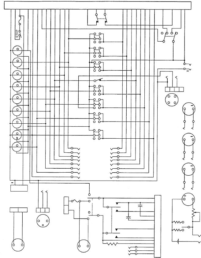
Figure 12-30.--Analyzer electrical schematic.
connectors; L1 through L9 indicate lights; S1 through
Refer to the schematic diagram and to figure 12-27
in discussing the analyzer's electrical system. In the
S14 represent switches; K1 through K33 indicate jack
diagram, letter symbols are used to indicate the
connections; M1 through M6 represent meters; and B1
different components of the system. The symbols R1
indicates the ohmmeter battery.
through R4 indicate resistors; C1 and C2 indicate
Five special cable assemblies and two pairs of
capacitors; T1 and T2 represent indicators; F1 and F2
represent fuses; J1 through J7 represent electrical
s p e c i a l l e a d s a r e p r ov i d e d f o r c o n n e c t i n g t h e
12-36