
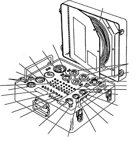
SENSITIVE AIR
PRESSURE GAGE
(STOWED IN
CASE TOP)
ISOLATION
SWITCHES
TEMPERATURE
THERMOCOUPLE
CONNECTOR
MAIN
CONNECTOR
OIL TEMPERATURE
GAUGE JACKS
TEST JACKS
28V DC INPUT
OIL TEMPERATURE
TEST LIGHTS
OIL PRESSURE GAUGE
BATTERY
OPERATION
SWITCHES
OIL PRESSURE
28V DC (RED)
FUEL PRESSURE
28V DC BATTERY
POWER (BLACK)
AIR OUT
CONTROL AIR
PRESSURE GAUGE
FUEL PRESSURE
CONTROL AIR
ASf12027
GAUGE
PRESSURE VALVE
AIR IN
Figure 12-27.--Gas turbine engine analyzer.
service installation provides the electrical power
analyzer may also be used for monitoring the turbine
necessary for the proper test functions of the analyzer.
unit during operation and for functional check of
Figure 12-28 is an illustration of an analyzer being
engine performance by controlling the load. It is also
used to test an engine while it is installed in the
used for static checks of engine components (such as
enclosure. As noted earlier, the analyzer may also be
powering the fuel solenoid valve without the engine
used with the engine installed in a test stand (fig.
operating) and to motor the engine for preservation and
12-29). The test stand supplies the fuel, oil, and
depreservation.
electrical power for both testing and operating the
The analyzer depends on electrical, fuel, oil, and
engine.
pneumatic systems connected to the engine through
The only required maintenance for the analyzer is
electrical cables, fuel, oil, and air pressure lines.
a periodic/calendar inspection. A preoperational
inspection is performed on the analyzer prior to each
ELECTRICAL SYSTEMS.--The analyzer's
use, and a calendar inspection is performed every 6
electrical system provides components for measuring
months. The calibration of gauges, meters, indicators,
turbine unit speed, exhaust temperature, and oil
etc., must be performed every 90 days or when
t e m p e r a t u r e . I t a l s o p r ov i d e s c o m p o n e n t s f o r
repaired, replaced, or when validity is questionable.
measuring engine-driven ac generator frequency,
electrical component resistance, current, and voltage.
The analyzer may be used for measurement of
Figure 12-30 shows a schematic wiring diagram of the
turbine unit speeds, temperatures, pressures, output
frequencies, and electrical circuit components. The
UPUA4-1 analyzer.
12-34