
WIRING DIAGRAMS
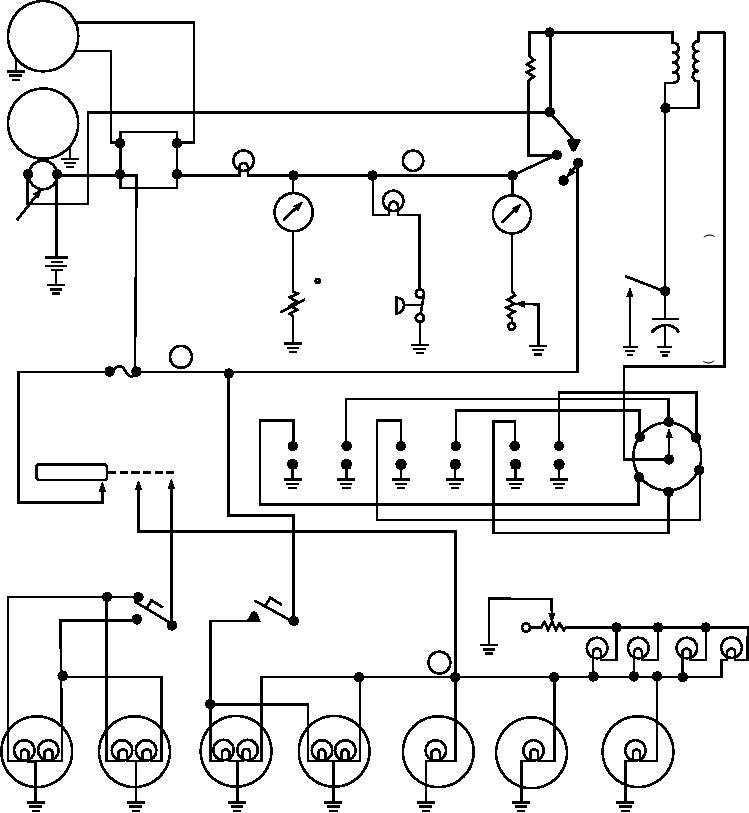
The major purpose of a schematic diagram (fig.
6-2) is to establish the electrical operation of a
Wiring diagrams (fig. 6-3) present detailed
particular system. It is not drawn to scale and shows
circuitry information concerning electrical systems. A
none of the actual construction details.
master-wiring diagram is a single diagram that shows
The schematic diagram is not your only tool in
all of the wiring in a complete system. In most cases,
troubleshooting electrical circuits. Wiring diagrams are
this diagram is too large to be usable. It is normally
also available to help you better understand system
broken down into logical functional sections, each of
operation.
F
IGNITION COIL
GEN
IGNITION
RESISTOR
IGNITION
SWITCH
S TA RT E R
GE N .
ON
LIGHT
A
F
S TA RT
3
B
T
S
OIL
OFF
O
V O LTA G E
WAT E R
PRESS.
L
R E G U L ATO R
T E M P.
LIGHT
E
GAS
B AT T E RY
N
GAUGE
C
C
O
A
O
I
POINTS
P
N
D
_T
GAS
A
D
WAT E R
GAUGE
C
OIL
E
T E M P.
TA N K
I
PRESS.
N
ELEMENT
UNIT
T
SWITCH
S
O
O
R
R
1
FUSE
D
I
2
S
6 T
4
R
LIGHT SWITCH
1
2
3
4
5
6
I
3B
1
P
U
ON
OFF
A
S PA R K
PLUGS
5
T
R
O
K
R
DIMMER
DIMMING
SWITCH
BRAKE
R H E O S TAT
LIGHTS
INSTRUMENT
PA N E L L I G H T S
2
R
L
R
L
R
L
TA I L S
T
B
D
B
D
ST
AND
TA G
S I D E PA N E L
HEAD
STOP
LIGHT
LIGHTS
LIGHTS
LIGHTS
ASf06002
Figure 6-2.--Schematic diagram.
6-2