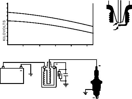
If the coil is connected so that polarity is reversed
battery's terminal posts and cables. Connections must
(spark plug center electrode positive), up to 40 percent
be clean, tight, and free of corrosion. Check for obvious
more voltage is required to fire the plugs (fig. 6-47).
damage in the primary wiring, such as broken or loose
This condition could result in hard starting, missing,
wires, or frayed insulation. All connections must be
and eventual coil failure.
clean and tight.
Pull the ignition coil's high voltage lead out of the
System Tests
coil tower. Check the tower for signs of corrosion or
burning. If it is corroded, clean it with a round brush or
There is a quick test you can use to try to localize
sandpaper wound around a pencil. Examine the tower
problems with the ignition system. First, remove the
carefully for any sign of flashover (high-voltage current
secondary coil lead from the distributor cap. Hold it
leaving the intended path and jumping down, or around,
approximately 3/16-inch from ground while you crank
directly to ground). Flashover can be caused by
the engine and observe the spark. A bright blue spark
moisture or dirt on the coil extender, a corroded tower
indicates proper operation of the primary circuit and the
interior, or by failing to have the high voltage lead
secondary winding of the ignition coil. That means that
pushed fully into the tower. If flashover has cracked the
troubleshooting can be limited to the distributor cap,
tower or left a burned path (carbon track), replace the
rotor, spark plug leads, and spark plugs. A yellow
coil. Check for correct coil polarity. The coil must be
spark, on the other hand, would indicate that the
connected into the primary circuit so that the positive
malfunction is in the primary circuit or the secondary
and negative markings of the coil correspond to the
winding of the ignition coil.
battery connections. In a negative grounded system, the
PRIMARY CIRCUIT TESTS.--Three basic
negative terminal of the coil must be connected to the
voltmeter tests can be made to isolate high resistance
distributor where it is grounded through the breaker
areas or components in the primary circuit. They are
points. By connecting the coil in this manner, the center
shown in views A, B, and C of figure 6-48.
electrode of the spark plug assumes a negative polarity.
NOTE: The voltage readings and test connections
It takes less voltage to cause electrons to move from
used here are for a 12-volt, negative ground system.
a hot to a cold surface. Since the center electrode of the
Always use the test specifications given by the
plug is always hotter than the side (ground) electrode,
manufacturer for any specific system.
current flow must be from the hot center electrode to
the cooler side electrode. By giving the center electrode
Battery-to-Coil Test.--Connect the voltmeter as
a negative polarity, current flows in this manner.
shown in figure 6-48, view A. Connect a jumper wire
20 TO 40% MORE VOLTAGE IS REQUIRED
WITH POLARITY REVERSED
REQUIRED
VOLTAG
E POS
ITIVE
POLA
REQUIRED V
RITY
OLTAGE
NEG AT
IVE P
HOTTER
OLAR
ITY
COOLER
ELECTRONS WILL MOVE
FROM A HOT OBJECT TO A
COLDER OBJECT AT A
LOWER VOLTAGE
ENGINE R P M
VOLTAGE REQUIRED AT SPARK PLUG
+
+
BATTERY
COIL
THE PRIMARY TERMINALS OF THE COIL MUST
BE CONNECTED SO THAT THE POLARITY MARKINGS
CORRESPOND TO BATTERY POLARITY.
ASf06047
Figure 6-47.--Correct coil polarity and current flow for a negative grounded system.
6-42

