
When the control circuit to the relay closes, it
plunger in, but once the plunger movement is complete,
creates a path for the current flow through the relay
the hold-in winding is sufficient to hold the plunger in.
winding. The magnetic field produced pulls the plunger
The pull-in winding is grounded through the very heavy
in and closes the heavy duty contacts. This energizes
winding of the starting motor. Closing the solenoid
the starting motor. When the control circuit opens,
contacts completes the power circuit to the starting
current flow through the relay winding stops and the
motor, and, at the same time, shorts out the pull-in
magnetic field collapses. The plunger releases and
winding.
returns to its original position by the return spring. This
When the ignition starter switch opens, current
opens the contacts and breaks the power circuit to the
flow through the control circuit stops and opens the
starting motor.
relay. However, the circuit through the hold-in winding
is still completed through the pull-in winding and the
Safety Controls
closed heavy duty contacts. Current flow through the
hold-in winding is in the same direction as when the
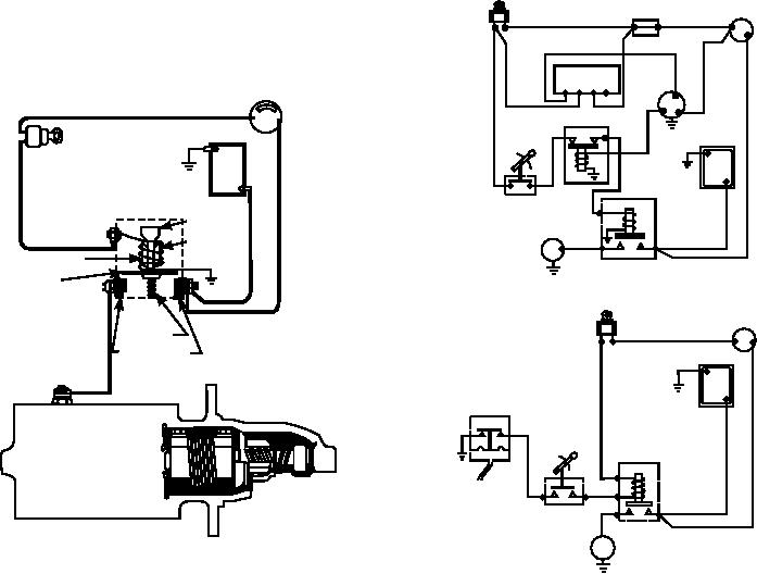
Safety controls are incorporated in support
control circuit was closed, but current flow through the
equipment starting systems to prevent engagement of
pull-in winding is now in the opposite direction. With
the starter after the engine is running. On self-propelled
the same number of turns in both windings and the
equipment, a safety control prevents the vehicle's
same current, the magnetic fields produced are equal
engine from starting unless the transmission shifter
but opposite and counteract each other. The plunger
lever is in a nondrive position (neutral or park). Two
releases and returns by spring tension to its original
examples are shown in figure 6-71.
position. This opens the heavy duty contacts and breaks
The safety devices discussed here may be used
the power circuit to the starting motor.
in any combination desired by the manufacturer.
Reference must be made to the applicable maintenance
Relay
manuals for the particular unit before you attempt to
troubleshoot or repair a starter control system.
A heavy duty relay is used with a starter that has a
Bendix drive (fig. 6-70). The purpose of the relay is to
JUNCTION
IGNITION/STARTER
BLOCK
complete the power circuit between the battery and the
SWITCH
A
starting motor. The relay is controlled by a low-current
remote circuit, which has a push-button switch or an
REGULATOR
ignition switch with a start position.
F23 4
F
AUX GEN
LOCKOUT-RELAY
B
SHIFT
BATTERY
BATTERY
LEVER
-
IGNITION/
STARTER
SWITCH
+
NEUTRAL
STARTER
RELAY
SAFETY SWITCH
RELAY OR
PLUNGER
(LINKAGE MOUNTED)
WINDING
S
CORE
A
CONTACT
DISK
IGNITION/STARTER
RETURN
SWITCH
SPRING
A
CONTACTS
BATTERY
-
+
LOCKOUT
SWITCH
SHIFT
STARTER
LEVER
RELAY OR
TO
OIL PRESSURE/
AIR PRESSURE
NEUTRAL
SAFETY SWITCH
(CASE MOUNTED)
ASf06070
S
B
Figure 6-70.--Control system for a starter with a Bendix
ASf06071
drive.
Figure 6-71.--Starter safety control combinations.
6-57