
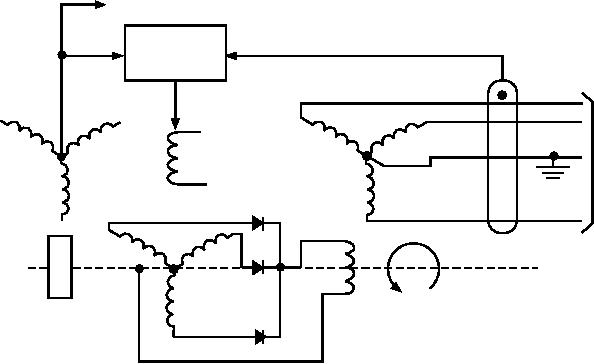
TO SYSTEM
CONTROL
V O LTA G E
R E G U L ATO R
A-C
S TATO R
O
U
EXCITER
PM
T
FIELD
S TATO R
P
U
T
N
GE N
O
SHAFT
S
ASf07034
Figure 7-34.--Diagram of a brushless ac generator excitation system.
control the amount of current the exciter may supply to
Pe r m a n e n t M a g n e t G e n e r a t o r . -- T h e
its control field. A decrease in the output ac voltage
permanent magnet generator (PMG) section consists
causes an increase in the exciter control field current.
of a permanent magnet rotor and a three-phase or
An increase in the output ac voltage causes a decrease
single-phase stator, depending on the particular model.
in the exciter control field current. The speed of the
The PMG is a simple, highly reliable source of power.
generator must be maintained to provide 400 Hz. All
The power generated by the PMG is used for
types of regulators perform the same functions, but
excitation, for operation of the electrical power control
a c c o m p l i s h t h e m t h r o u g h d i ff e r e n t o p e r a t i n g
relays, and for operation of the electrical protective
principles.
system. Since the PMG operates at a constant speed, its
output voltage is constant and completely independent
The ac voltage regulator is usually a complicated
of the main generator's output. The PMG continues to
design. The schematic shown in figure 7-35 is a
deliver power during a failure of the main generator.
simplified basic circuit. It is used as a matter of
This arrangement provides positive control of the main
simplicity in explaining the principles of ac voltage
generator. The PMG ensures that a source of power is
regulating.
The voltage regulator is a static unit that samples
Excitation is not dependent on a residual flux being
one phase of the generator output. It is compared to a
present in the generator or exciter. The PMG excitation
reference voltage and biases an output amplifier with
system is designed to operate transistors at their
the differential signal. Varying the gain of the output
optimum voltage. This prevents exposure of the
amplifier varies the dc current passing through the
transistors to the harmful transient voltages present
windings of the exciter. The exciter applies a varying
during fault or load-switching conditions of the main
current to the generator field coils. This simultaneous
generator system.
action varies the generator voltage output.
The PMG section of a brushless generator is a
One phase of voltage is taken from the generator
simple, reliable source of power. The PMG makes the
and applied across the primary side of transformer T1
brushless generator a completely self-contained unit
and resistor R1. The secondary output of T1 is applied
that does not depend on an external source of power for
to full-wave rectifiers, CR1 and CR2. The ripple
buildup or excitation during operation.
component of the output is reduced by the LC filter
network consisting of L1 and C4. The output of T1 is
AC Voltage Regulators
dropped by R2 and Zener diode VR2. This provides a
The essential function of the voltage regulator is to
reference voltage for R14 and the base of Q3. The
output of T1 is also applied to the voltage divider
use the ac output voltage as a sensing influence to
7-26